
Ambient noise root mean square (RMS) detector

Active Publication Date: 2014-08-14
CIRRUS LOGIC INC
View PDF0 Cites 31 Cited by
  • Summary
  • Abstract
  • Description
  • Claims
  • Application Information

AI Technical Summary

Benefits of technology

The present ambient noise RMS detector provides a background RMS value that is largely immune to sudden spikes in value caused by speech, "scratching," and wind noise. This is achieved by calculating the previous RMS value and its smoothed version, and using them to generate a reset signal for the minimum tracker. The effect of the detector is to improve the accuracy and reliability of the ambient noise measurement.

Problems solved by technology

The problem with the Cohen design is that it is susceptible to non-stationary noise such as spike noise.
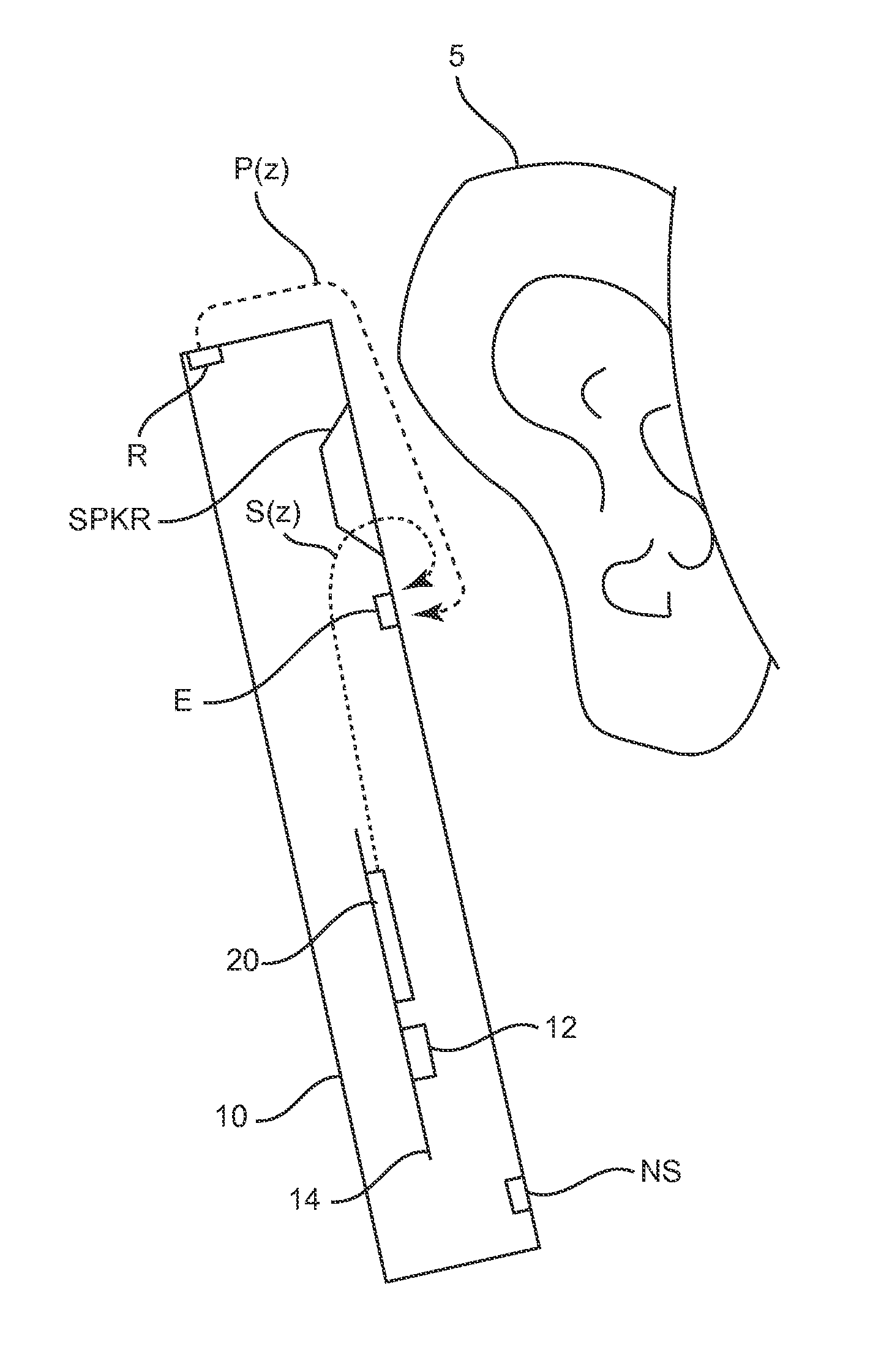
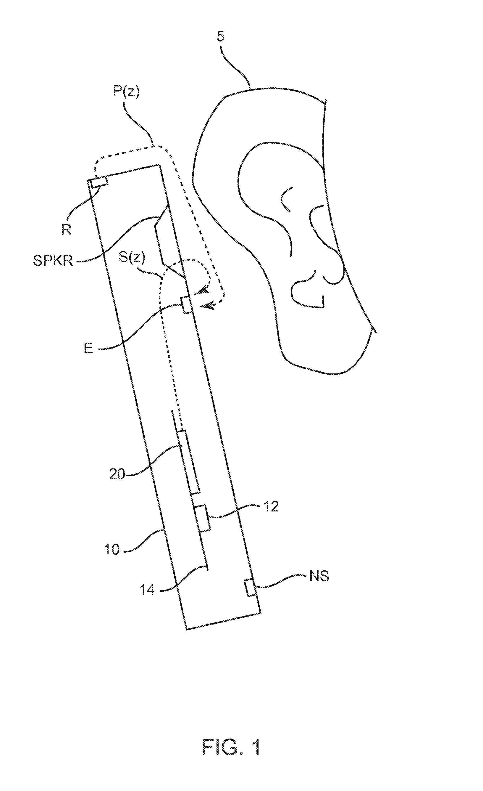
For example, when used in an adaptive noise cancellation system (ANC) on a cellular phone or the like, spike noise such as wind noise or scratching (user's / talker's hand scratching or rubbing the case) may create spikes to which the Cohen design would over-react.
As a result, the performance of an ANC system, for example, in a cellular telephone or the like, may be degraded, as the rms detector over-reacts to these spike noises.
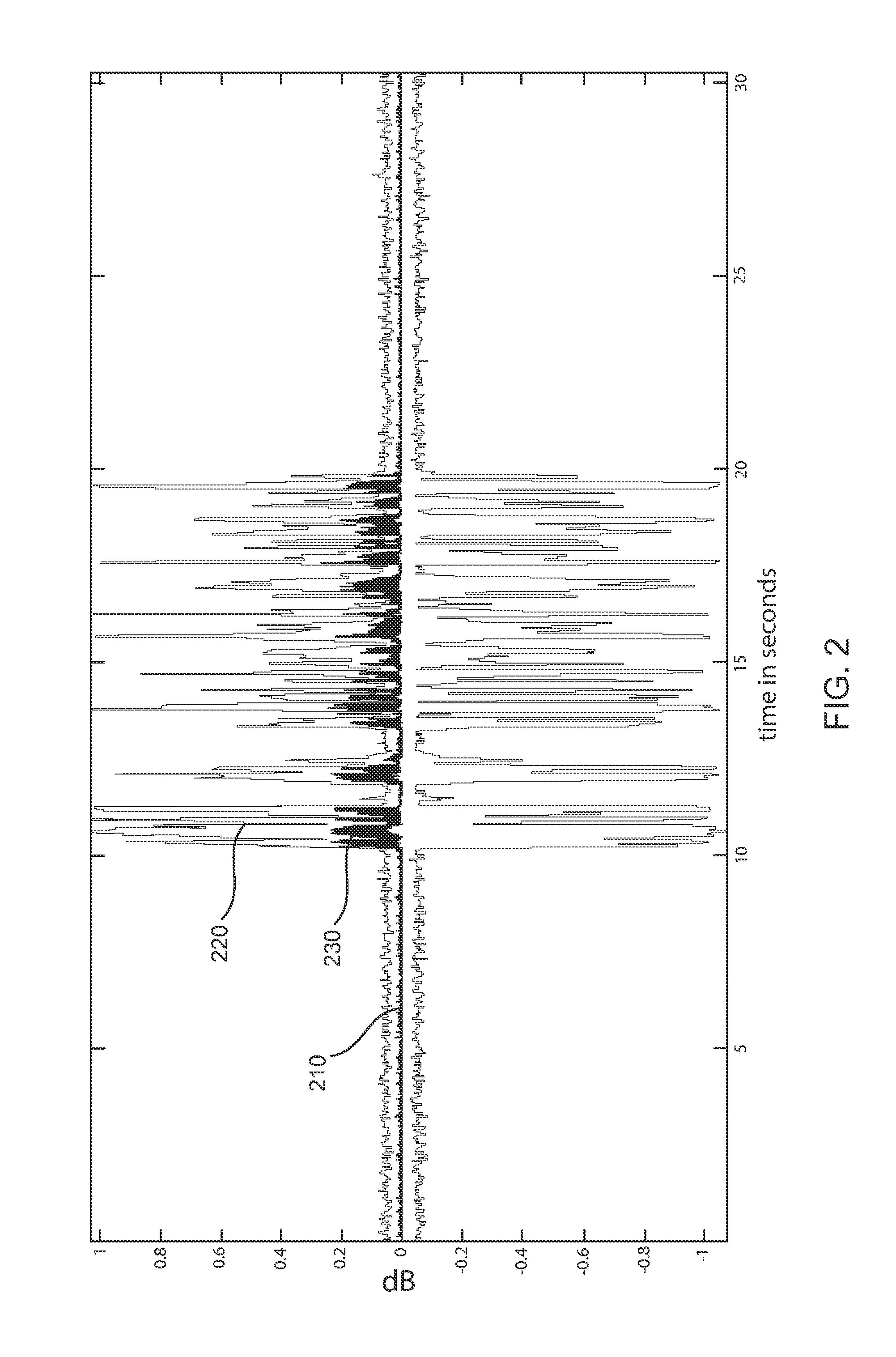
The problem with such a simple rms detector is that it not only tracks background noise, but also speech, scratch, and wind noise.
By tracking the spike signals 220, the ANC circuit may end up generating inappropriate anti-noise, and as a result, create artifacts in the reproduced audio signal for the user.

Method used


Image

  • Ambient noise root mean square (RMS) detector
  • Ambient noise root mean square (RMS) detector
  • Ambient noise root mean square (RMS) detector

Examples


Embodiment Construction

[0029]The present ambient noise RMS detector improves upon the techniques of prior art rms detectors such as taught by Martin and Cohen by using an improved algorithm in the RMS detector. FIG. 3 is a block diagram of the present ambient noise RMS detector. Referring to FIG. 3, a raw rms value is calculated from the input signal using known prior art techniques. Blocks 110, 120, and 130 are elements of a first-order regressor with a variable smoothing factor. The input signal, which in this instance may be a background noise signal with speech, is fed to block 110 where the absolute value of the signal is taken. This absolute value signal in turn is fed to low-pass-filter 120 and then to downsampler 130. The net effect is to output a raw rms value such as described above in connection with Equation (1). As these first three elements of the block diagram are known in the art, they will not be described in further detail.

[0030]Both the Martin and Cohen methods and designs discussed abo...


PUM


Abstract

An RMS detector uses the concept of the k-NN (classifying using nearest neighbors)-algorithm in order to obtain RMS values. A rms detector using first-order regressor with a variable smoothing factor is modified to penalize samples from center of data in order to obtain RMS values. Samples which vary greatly from the background noise levels, such as speech, scratch, wind and other noise spikes, are dampened in the RMS calculation. When background noise changes, the system will track the changes in background noise and include the changes in the calculation of the corrected RMS value. A minimum tracker runs more often (e.g. two or three times) than the rate as in prior art detectors and methods, tracks the minimum rms value, which is to compute a normalized distance value, which in turn is used to normalize the smoothing factor. From this data, a corrected or revised RMS value is determined as the function of the previous RMS value multiplied by one minus the smoothing factor plus the smooth factor times the minimum rms value to output the corrected RMS for the present invention. The rms value is used to generate a reset signal for the minimum tracker and is used to avoid deadlock in the tracker, for example, when the background signal increases / decreases over time.

Description

FIELD OF THF INVENTION[0001]The present invention relates to an ambient noise Root Mean Square (RMS) level detector. In particular, the present invention is directed toward an improved noise RMS detector that is robust to speech presence, wind noise, and other sudden variations in noise levels.BACKGROUND OF THF INVENTION[0002]A personal audio device, such as a wireless telephone, includes an adaptive noise canceling (ANC) circuit that adaptively generates an anti-noise signal from a reference microphone signal and injects the anti-noise signal into the speaker or other transducer output to cause cancellation of ambient audio sounds. An error microphone is also provided proximate the speaker to measure the ambient sounds and transducer output near the transducer, thus providing an indication of the effectiveness of the noise canceling. A processing circuit uses the reference and / or error microphone, optionally along with a microphone provided for capturing near-end speech, to determi...

Claims


Application Information

Patent Timeline
IPC IPC(8): H04R29/00
CPCH04R29/00G10K2210/108G10K2210/3023G10L21/0216G10L2021/02165G10K11/1785G10K11/17881G10K11/17837G10K11/17823H04R29/004G10L21/0224
Inventor ABDOLLAHZADEH MILANI, ALI
Owner CIRRUS LOGIC INC
Learn More