
Multiple axle equalizing rubber suspension

Active Publication Date: 2014-08-14
TRANSPORTATION TECH
View PDF6 Cites 2 Cited by
  • Summary
  • Abstract
  • Description
  • Claims
  • Application Information

AI Technical Summary

Benefits of technology

The invention is a suspension system for vehicles that reduces the spring rate and provides a better ride. It includes a frame mounting bracket, first and second levers, rubber torsion axle assemblies, a control arm, spindle swing arms, and rubber springs. The system is designed to absorb loads and prevent overloads on single axles, resulting in a longer life for the rubber torsion system.

Problems solved by technology

However, the spindle of the suspension of U.S. Pat. No. 7,758,056 rides at load position where the torsion axle is already partly compressed limiting the range of motion available of the spindle with respect to a no-load position.
Also, when two or more torsion axle assemblies without any air suspension components are used in a suspension system there is no equalization of loads between the two or more torsion axle assemblies.

Method used


Image

  • Multiple axle equalizing rubber suspension
  • Multiple axle equalizing rubber suspension
  • Multiple axle equalizing rubber suspension

Examples


Embodiment Construction

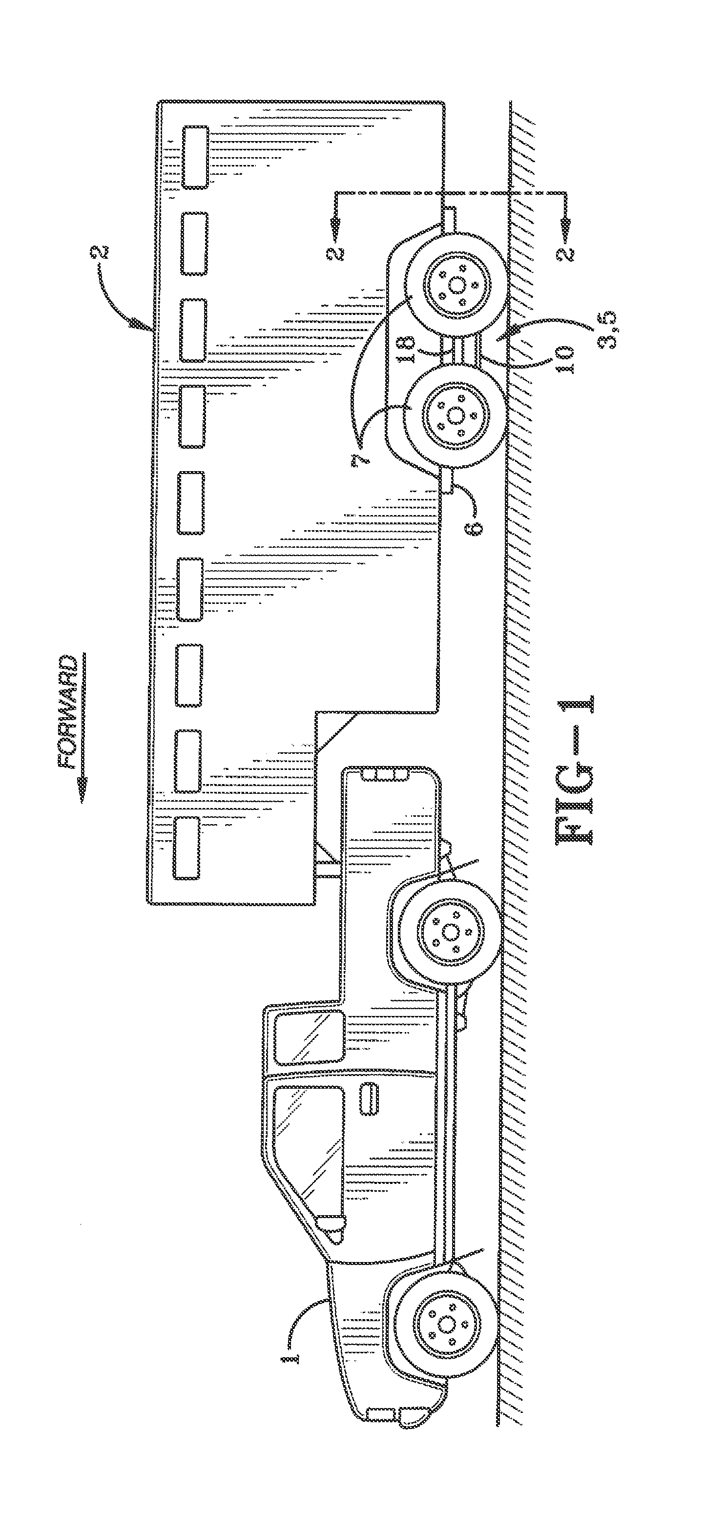
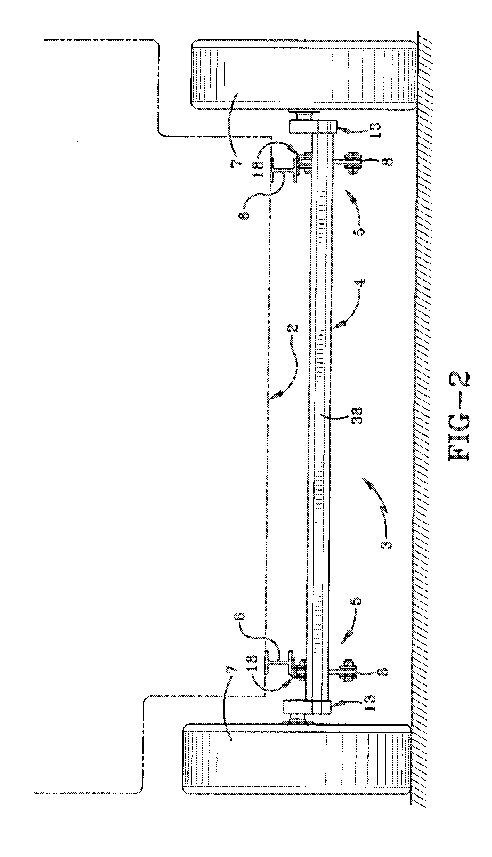
[0047]FIG. 1 illustrates an example midsized trailer 2 that is pulled by a truck 1. The preferred embodiment of a vehicle suspension system indicated generally at 3 is mounted to the trailer 2 and is used to equalize loads on both axles and soften the force encountered by its wheels 7. The suspension system 3 can be mounted to other trailers of different sizes and in some configurations might even be mounted to a frame rail 6 of the trailer 2 or directly to a truck 1 itself as FIG. 1 merely illustrates one example of where the suspension system 3 is used and does not limit other potential uses.

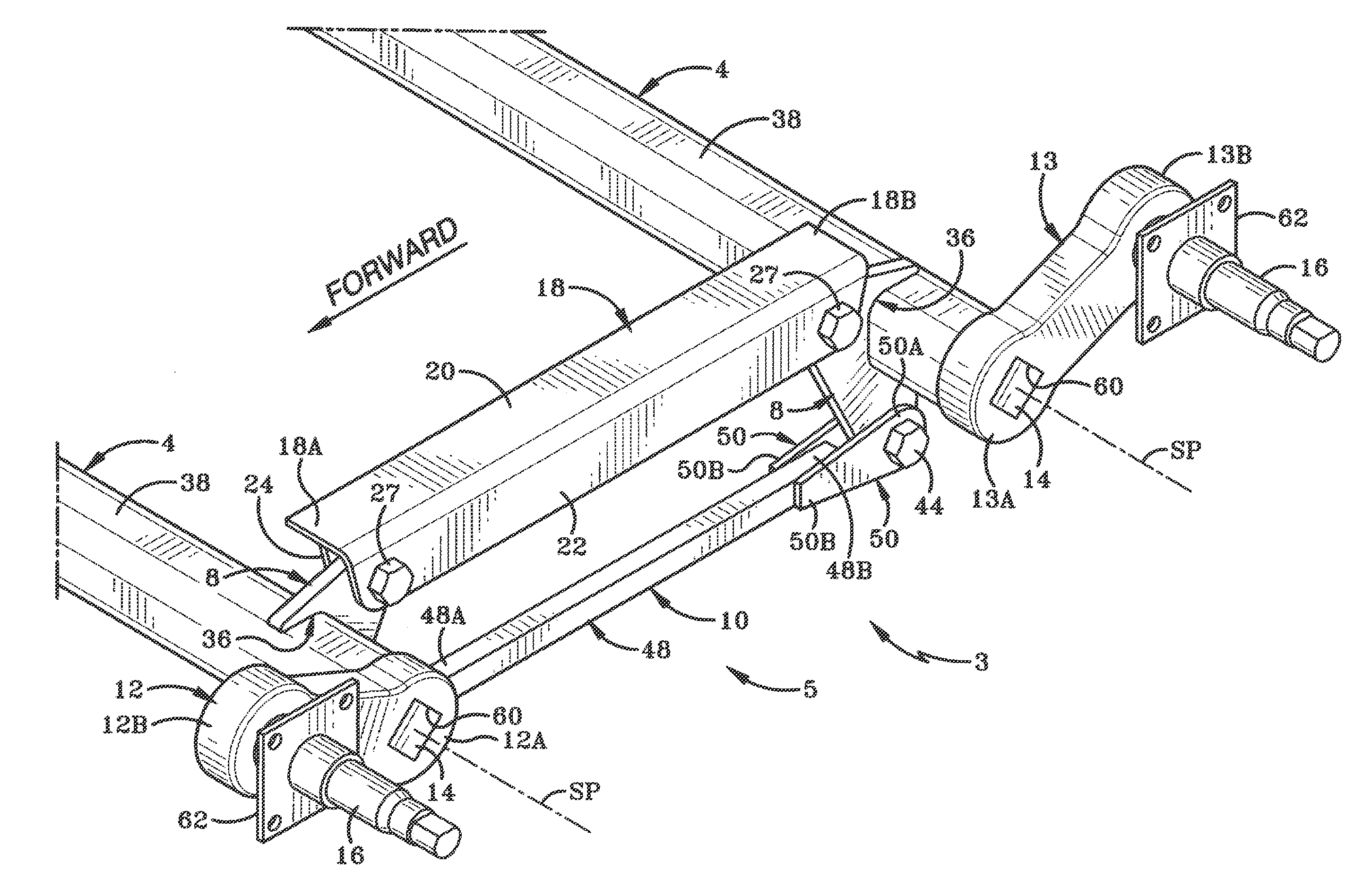
[0048]Before describing the preferred embodiment of the suspension system 3 in detail, the following are briefly discussed: first, a paragraph introduces a preferred embodiment of an improved new suspension assembly 5 (FIG. 3) that includes two torsion axle assemblies 4, two levers 8 and a control arm 10; secondly, a paragraph discusses the benefits of a suspension assembly 5 with the two leve...


PUM


Abstract

A suspension system for a vehicle includes a frame mounting bracket for mounting to the vehicle. The suspension includes front and rear rubber torsion axle assemblies. Front and rear lever assemblies are respectively pivotally attached to the vehicle at front and rear lever pivot points. Outer housings of the rubber torsion axle assemblies are each respectively rigidly mounted to the front and rear lever assemblies. A rigid control arm is pivotally connected at one end to the front lever assembly at a front control arm pivot point and its other end is pivotally connected to the rear lever assembly at a rear control arm pivot point. When the suspension assembly encounters a force causing the front lever assembly to rotate in one direction about the front lever pivot point the rigid control arm causes the rear lever assembly to rotate about the rear lever pivot in an opposite direction.

Description

CROSS REFERENCE TO RELATED APPLICATION[0001]This application claims priority from U.S. patent application Ser. No. 13 / 765,736, filed Feb. 13, 2013; the disclosure of which is incorporated herein by reference.BACKGROUND[0002]1. Technical Field[0003]The invention relates to suspension methods and systems for vehicles such as trailers and trucks. More particularly, the invention relates to a suspension system using two or more rubber torsion axle assemblies that operate together. Specifically, the invention relates to a torsion axle assembly being linked to a second torsion axle assembly to improve axle-to-axle load equalization and provide for a softer ride.[0004]2. Background Information[0005]Torsion axles have been known for many years such as those shown in U.S. Pat. No. 2,998,981 for example. Torsion axles have proven to be extremely popular because if one wheel hits a bump or rut it can react independently of the other wheel which may not have hit a bump or rut at the same time. ...

Claims


Application Information

Patent Timeline
IPC IPC(8): B60G11/18
CPCB60G11/18B60G5/04B60G11/225B60G2300/04
Inventor VANDENBERG, ERVIN K.CROSTON, DAVID H.POWERS, MICHAEL K.
Owner TRANSPORTATION TECH
Learn More