Correction of asymmetric electric fields in ion cyclotron resonance cells

a technology of cyclotron resonance and ion cyclotron, which is applied in the direction of calibration apparatus, instruments, separation processes, etc., can solve the problems of ion loss during cyclotron excitation, increase of peak intensity, and interference of detected signals

Active Publication Date: 2014-08-14
BRUKER DALTONIK GMBH & CO KG
View PDF1 Cites 8 Cited by
  • Summary
  • Abstract
  • Description
  • Claims
  • Application Information

AI Technical Summary

Benefits of technology

[0025]As set out initially, normally the axis of the magnetron motion is expected to coincide with the ICR cell axis, but occasionally the axis of the ionic magnetron orbit in an ion cyclotron resonance cell (ICR cell) shows a radial offset from the geometric axis of the cell. An offset of the magnetron orbit negatively influences the cyclotron excitation process of the ions and their detection. It also impairs the detected signal, leads to an increase of the intensity of the peaks associated with the even-numbered (e.g., second) harmonics in the Fourier transformed spectrum and to more abundant sidebands of the ion signal. In extreme cases, ions can be lost during the cyclotron excitation when they are on large and offset magnetron orbits that are critically close to the cylinder mantle electrodes. Aspects of the present invention describe a method (and a device) for the correction of asymmetric electric fields in an ICR cell that lead to offset magnetron orbits. The method helps identifying a displacement of the electric field axis and / or trimming the correspondingly displaced magnetron axis back to the cell axis.

Problems solved by technology

It also impairs the detected signal, leads to an increase of the intensity of the peaks associated with the even-numbered (e.g., second) harmonics in the Fourier transformed spectrum and to more abundant sidebands of the ion signal.
In extreme cases, ions can be lost during the cyclotron excitation when they are on large and offset magnetron orbits that are critically close to the cylinder mantle electrodes.
Any distortion / asymmetry of the electric field or improper injection of an ion into the ICR cell, however, entails a magnetron motion of the ions in the ICR cell.

Method used


Image

  • Correction of asymmetric electric fields in ion cyclotron resonance cells
  • Correction of asymmetric electric fields in ion cyclotron resonance cells
  • Correction of asymmetric electric fields in ion cyclotron resonance cells

Examples


Embodiment Construction

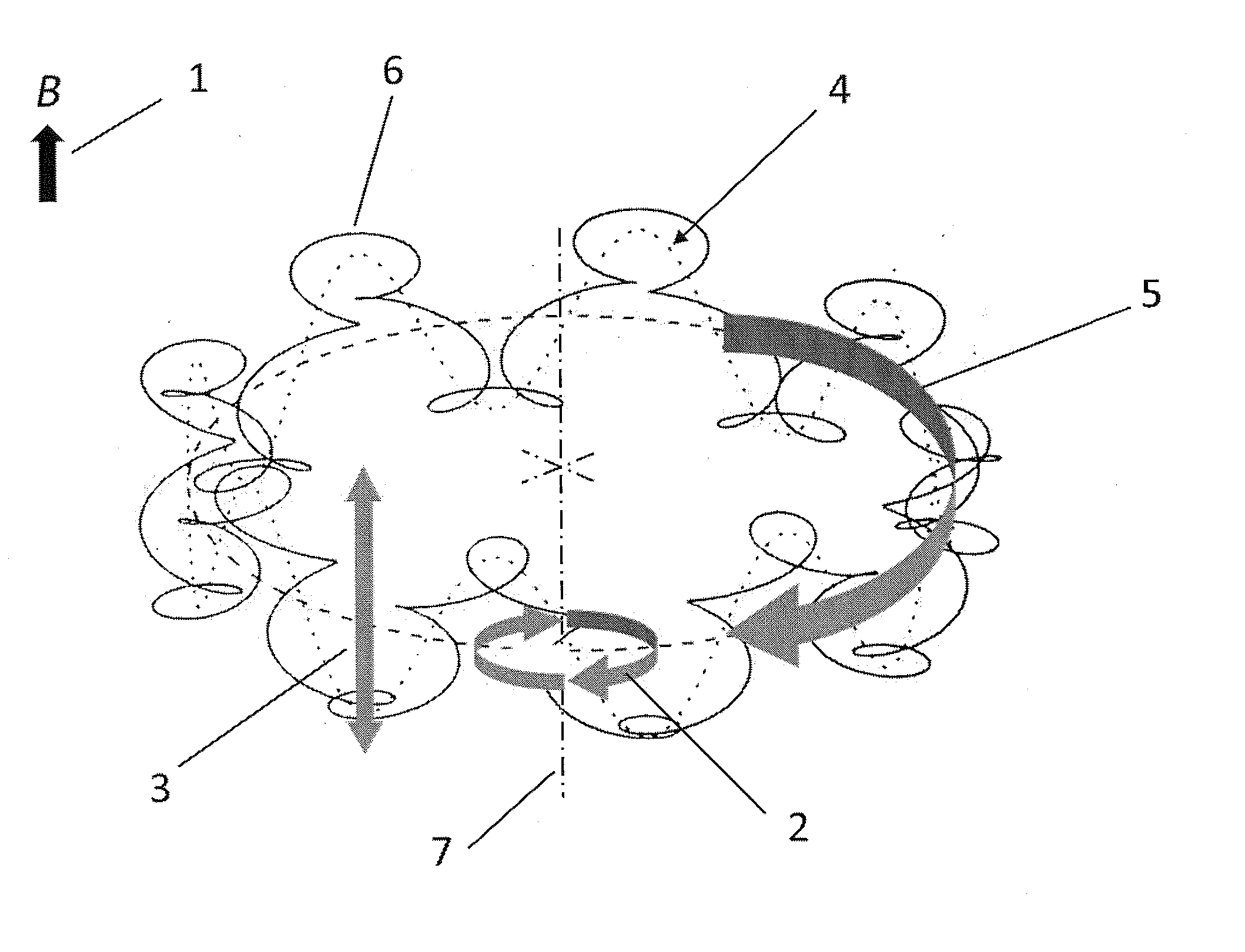
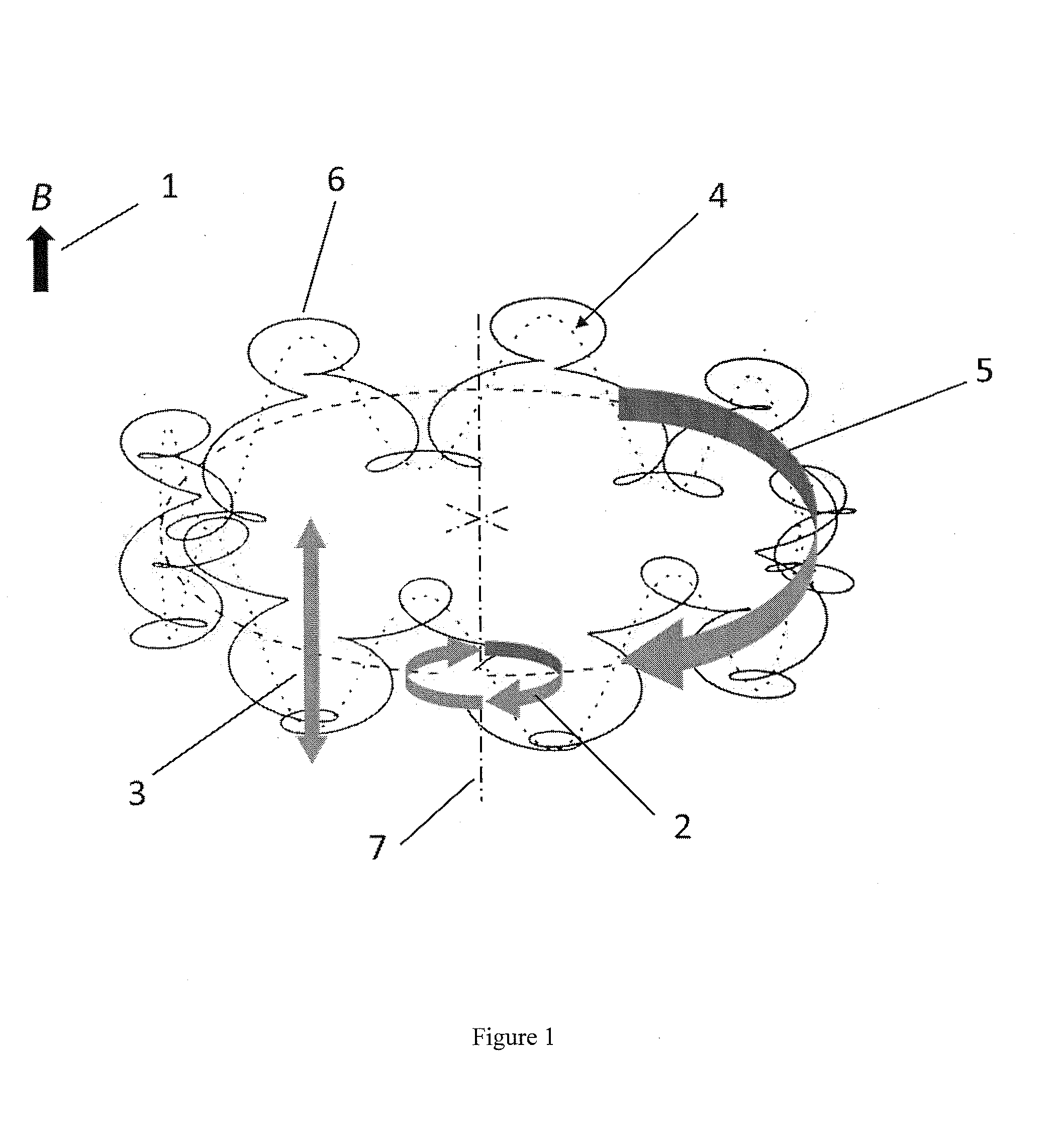
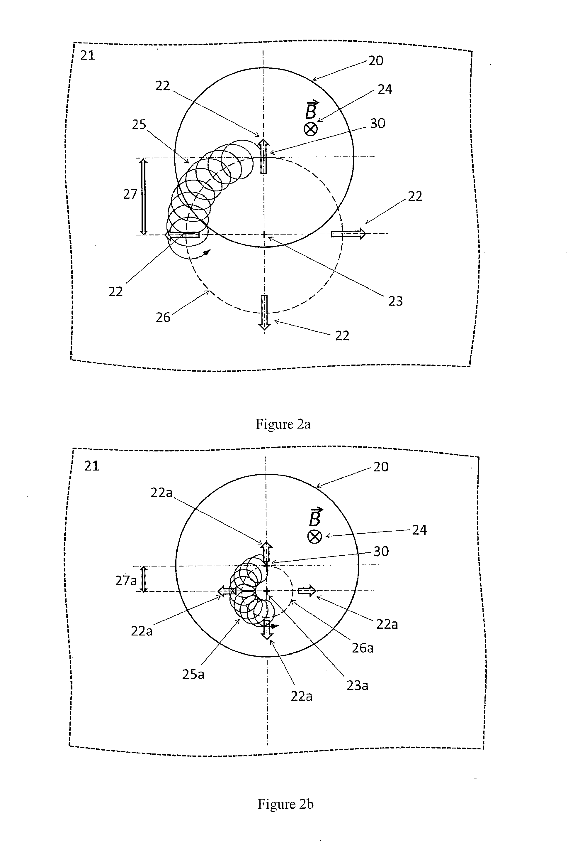
[0049]In one embodiment, the present invention aims at detecting an electric field asymmetry in the ICR cell and eliminating it by compensating and correcting the electric field.

[0050]The existence of the magnetron motion in the cell produces normally very weak sidebands around the main ion cyclotron resonance signal of an ion measured at the frequency vR which are on the frequency scale in a distance of the magnetron frequency vM and 2vM. Additionally, in the mass spectrum a peak with half the mass, i.e., with the doubled reduced cyclotron frequency (2vR) appears, this is the peak of the second harmonic. Another signal with comparable abundance appears in the direct vicinity of the 2vR signal, which is a satellite peak with a frequency of (2vR+vM). This satellite peak is separated from the second harmonics by just a magnetron frequency (vM). The mass difference is e.g., at m / z 351 about 0.007 dalton. Depending on conditions, also other satellite signals with even less abundance can...


PUM


Abstract

The invention relates to a method and a device for optimization of electric fields in measurement cells of Fourier transform ion cyclotron resonance mass spectrometers. The invention is based on the rationale that asymmetric electric fields with uniformly or non-uniformly perturbed field axes can appear in ion cyclotron resonance cells and therefore the axis of the magnetron orbit can become radially displaced. Shifted magnetron orbits negatively affect the cyclotron excitation, deteriorate the FT-ICR signal, increase the intensity of an even-numbered harmonics peak, lead to stronger side bands of the FT-ICR signal, and in extreme cases, cause loss of ions. The present invention helps in probing the shift of the magnetron motion, detecting parameters indicative of the offset of the electric field axis and / or correcting it by trimming it back to the geometric axis of the cell.

Description

FIELD OF THE INVENTION[0001]The invention relates to methods and devices for the compensation of asymmetric electric fields in the measurement cells of Fourier transform ion cyclotron resonance mass spectrometers (FT-ICR MS).BACKGROUND OF THE INVENTION[0002]The cyclotron radius rc, of an ion with the mass m, the elementary charge e, the charge number z, and the kinetic energy Ekin in a magnetic field of the flux density B is given by the following equation:rc=2mEkinzeB(1)In the thermal energy range, e.g., at a temperature of 298 K, and in a magnetic field with the flux density of 7 Tesla, the cyclotron radius of a singly charged ion with mass 1,000 dalton is approximately a tenth of a millimeter. Normally, the ICR cell contains a large number of ions, and their masses can be quite different. Before detection, the cyclotron motion of the ions is excited by an oscillating (RF) electric field with a scanned frequency (“Chirp”). When the frequency of the scanned oscillating field become...

Claims


Application Information

Patent Timeline
Patent Type & Authority Applications(United States)
IPC IPC(8): H01J49/00
CPCH01J49/0009H01J49/38
Inventor BAYKUT, GOEKHANFRIEDRICH, JOCHENJERTZ, ROLANDKRIETE, CLAUDIA
Owner BRUKER DALTONIK GMBH & CO KG
Why Eureka
Try Eureka