Impact Protection for Implantable Electric Lead

a technology of implantable electric leads and impact protection, which is applied in the field of medical implants, can solve the problems of reducing the flexibility of the electrode, affecting the location of the affected wire, and affecting the stability of the implant housing,

Active Publication Date: 2014-07-31
MED EL ELEKTROMEDIZINISCHE GERAETE GMBH
View PDF6 Cites 9 Cited by
  • Summary
  • Abstract
  • Description
  • Claims
  • Application Information

AI Technical Summary

Benefits of technology

The patent describes an electric lead design for a medical implant system that helps protect the lead wires from external impact force. The lead consists of parallel lead wires wound in an elongated helix around a central axis, and at least one support wire that is more flexible and strong than the lead wires. There is also a protective ribbon that wraps around the lead wires to further shield them from impact. These features make the electric lead arrangement more durable and less prone to damage during implantation and use.

Problems solved by technology

Lead wires at the affected location experience local tensile forces and can even break.
One disadvantage of such designs in the case of cochlear implants is that the implant housing must be placed in a very exactly defined position relative to the ear.
For implant designs where the electrode lead emerges from the side of the implant housing, the surgeon is recommended to drill an electrode channel into the bone, which is time consuming so that not every surgeon follows the recommendations.
Some electrode lead design include a rigid impact protector that surrounds the electrode lead, but that approach reduces the flexibility of the electrode lead which in turn makes the surgical implantation procedure more difficult.
And in case of a mechanical impact in the area of the electrode lead, a rigid impact protector may protect the electrode from damage but also may cause trauma in the surrounding tissue when it is pressed against the protector.

Method used


Image

  • Impact Protection for Implantable Electric Lead
  • Impact Protection for Implantable Electric Lead
  • Impact Protection for Implantable Electric Lead

Examples


Embodiment Construction

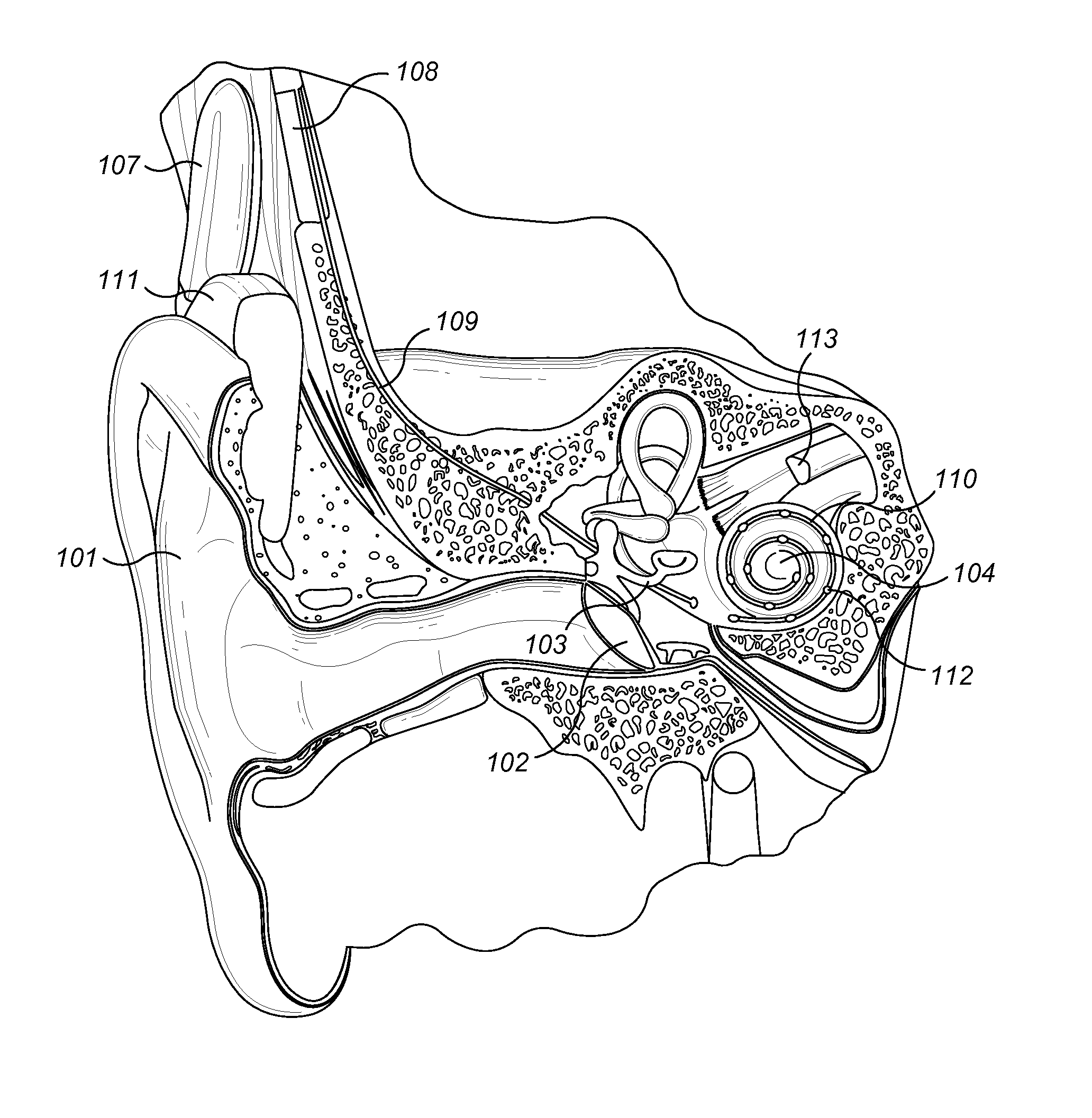
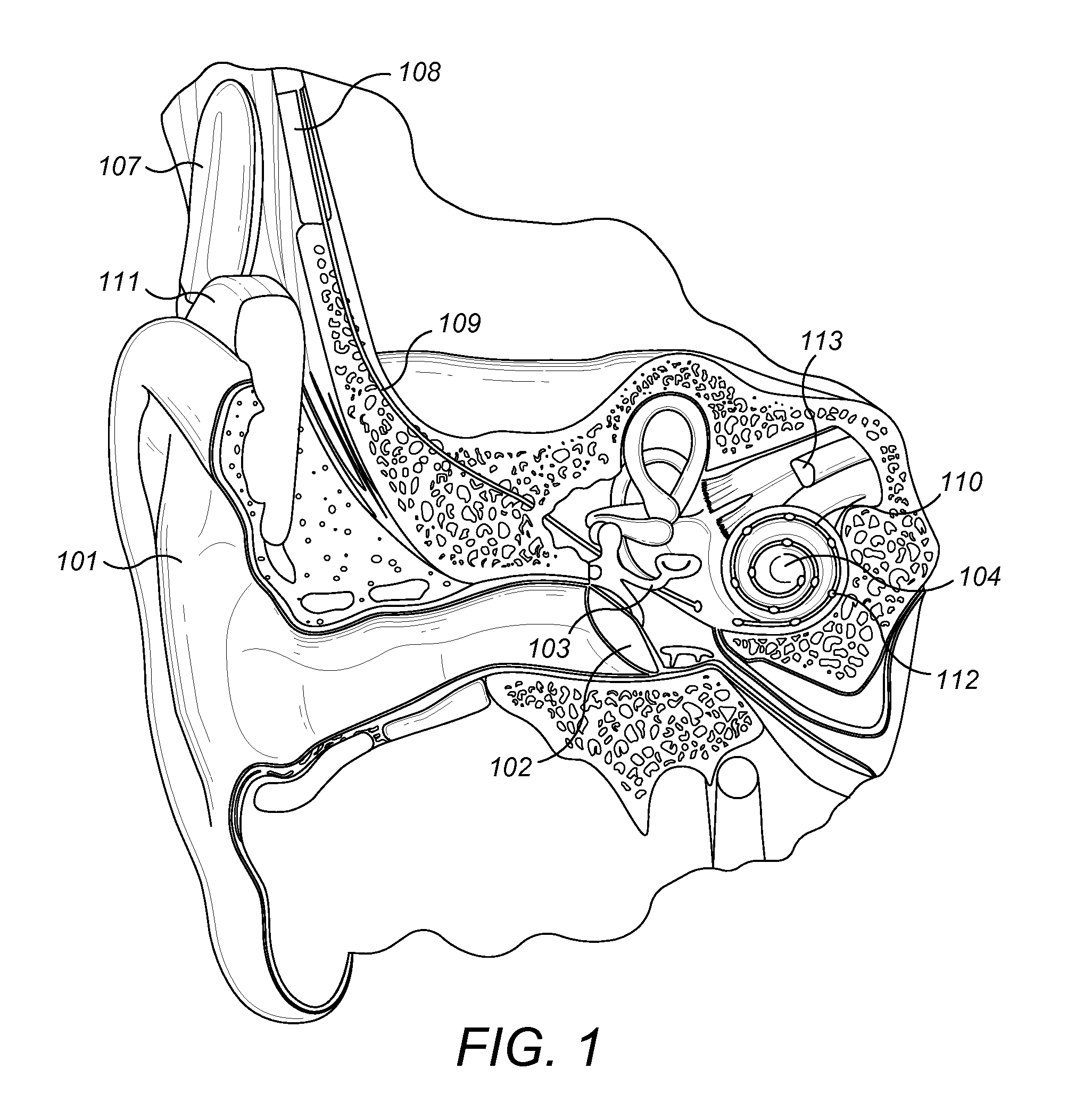
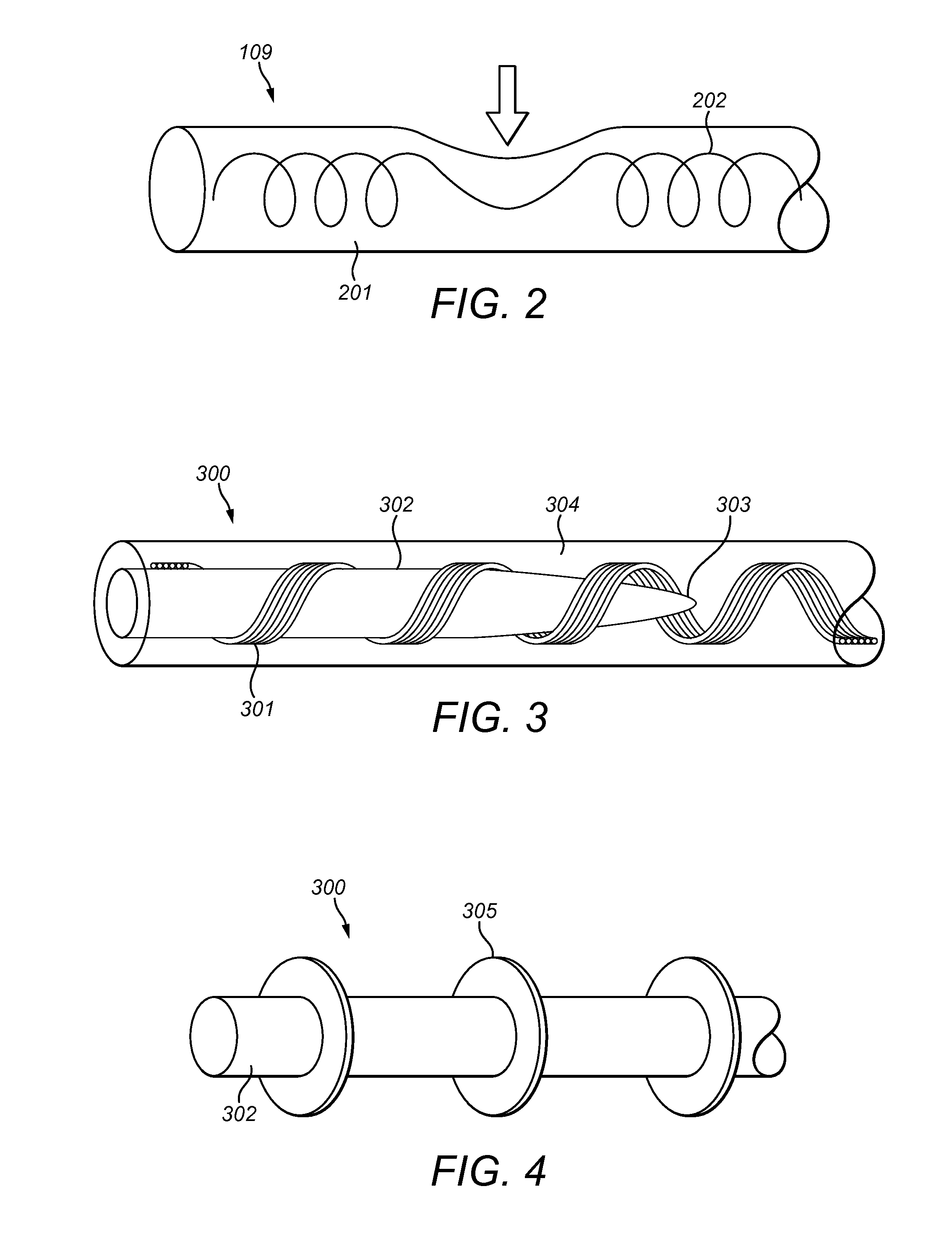
[0027]FIG. 2 shows how longitudinal deformation of a cochlear implant electrode lead 109 occurs in response to radial and / or axial deformation caused by an external impact or exerted pressure onto the electrode lead 109 which thins and elongates the resilient material of the lead carrier 201 and creates a local tensile force on the lead wires 202. Such longitudinal deformation should be prevented or strongly suppressed. Reduced longitudinal deformation as a response to radially induced deformation is especially a challenge in electric leads 109 having helically wound lead wires 202 as in FIG. 2. Embodiments of the present invention are directed to an implantable electric lead, for example, a cochlear implant electric lead 109, which is more robust against radial and / or axial deformation to avoid wire breakage within the electric lead 109. This most often occurs relatively close to the stimulator housing where after implantation the electric lead 109 runs on top of the skull bone.

[00...


PUM


Abstract

A novel implantable electric lead arrangement is described for medical implant systems such as middle ear implants (MEI), cochlear implants (CI) and vestibular implants (VI). An electric lead contains parallel lead wires wound in an elongated helix about a central longitudinal axis. A lead core is fixed and enclosed within the wire helix for providing impact strain relief to the lead wires by resisting radial and / or axial deformation from external impact force.

Description

[0001]This application claims priority from U.S. Provisional Patent Application 61 / 756,502, filed Jan. 25, 2013, which is incorporated herein by reference in its entirety.FIELD OF THE INVENTION[0002]The present invention relates to medical implants, and more specifically to an implantable electrode arrangement used in medical implant systems such as middle ear implants (MEI), cochlear implants (CI) and vestibular implants (VI).BACKGROUND ART[0003]A normal ear transmits sounds as shown in FIG. 1 through the outer ear 101 to the tympanic membrane (eardrum) 102, which moves the bones of the middle ear 103 (malleus, incus, and stapes) that vibrate the oval window and round window openings of the cochlea 104. The cochlea 104 is a long narrow duct wound spirally about its axis for approximately two and a half turns. It includes an upper channel known as the scala vestibuli and a lower channel known as the scala tympani, which are connected by the cochlear duct. The cochlea 104 forms an up...

Claims


Application Information

Patent Timeline
IPC IPC(8): A61N1/05
CPCA61N1/0541
Inventor ZIMMERLING, MARTINBEAL, FABRICEDE LUCA, DAVIDEHAMMERER, DOMINIKHOFER, STEFANSCHINDLER, PHILIPP
Owner MED EL ELEKTROMEDIZINISCHE GERAETE GMBH
Why Eureka
Try Eureka