
Driving wheel of robot moving along the wire and robot having the same

a technology of a robot and a wire, which is applied in the direction of rope railways, manufacturing tools, and ways, can solve the problems of high risk of safety accidents or like, metal fittings can be an obstacle to the robot's mobility, and high risk of falling off the transmission line, so as to prevent the separation of the wire

Inactive Publication Date: 2014-07-31
KOREA INST OF SCI & TECH
View PDF14 Cites 74 Cited by
  • Summary
  • Abstract
  • Description
  • Claims
  • Application Information

AI Technical Summary

Benefits of technology

This patent describes a driving wheel for a robot that moves along a wire such as a transmission line inspection robot. The driving wheel has an inner wheel and an outer wheel that surrounds it and sits on the wire. A shock absorbing support connects and supports the inner and outer wheels, and it absorbs any shocks or changes in movement caused by external forces. The outer wheel is made of elastic material and can change shape when an external force is applied or removed. The spokes in the shock absorbing support are made of elastic material and are formed in a slanted manner. The robot also has a wire reception groove on the outer wheel to prevent separation of the wire. Overall, this invention allows the robot to move stable along the wire and inspect the condition of the transmission line as it moves along.

Problems solved by technology

Currently, transmission line inspection mainly relies on visual inspection by a skillful technician who goes up to a transmission line in person and inspects the transmission line with the naked eye, and has a very high risk of safety accidents or like.
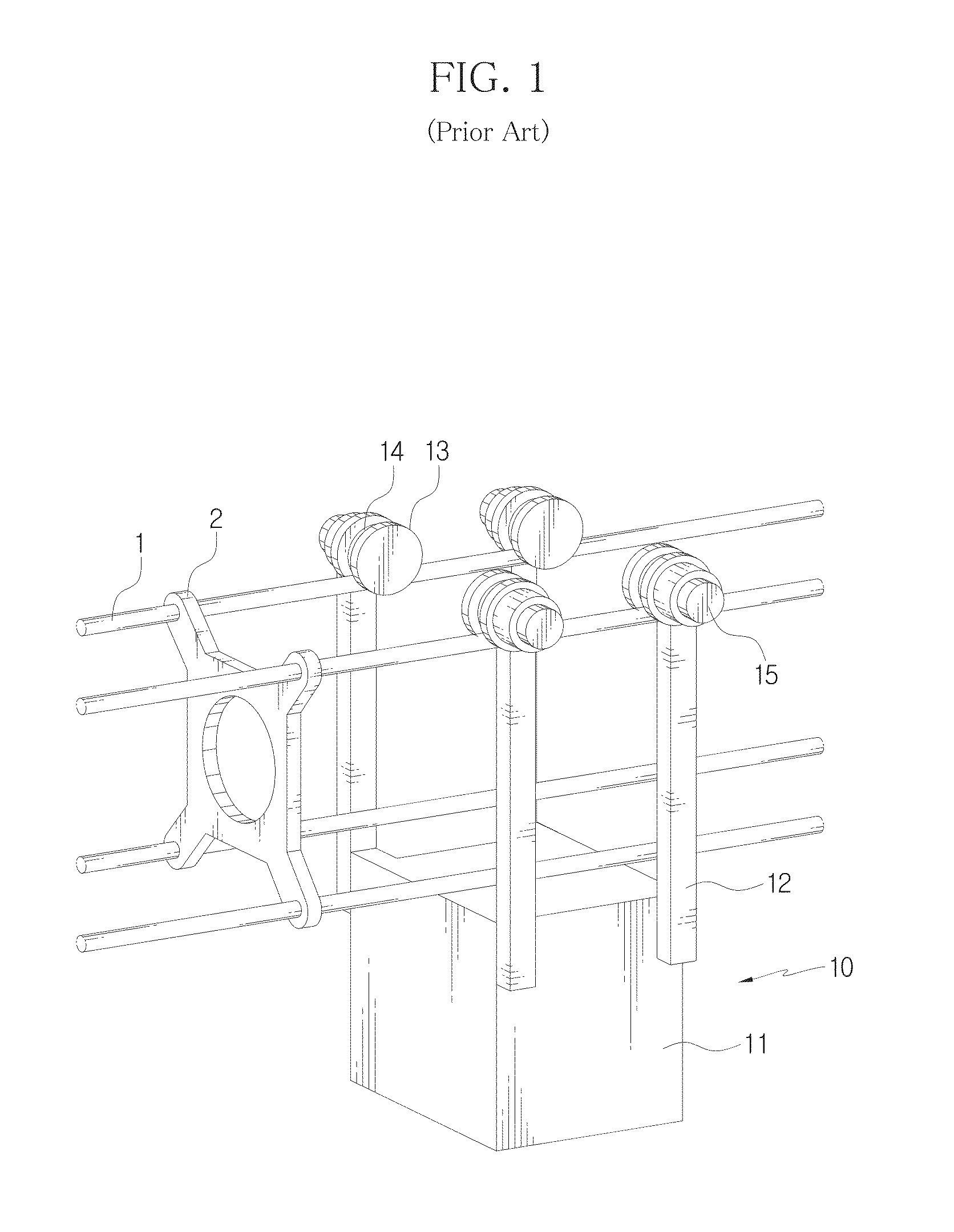
Because a majority of metal fittings have a greater cross-sectional area than the transmission line 1, the metal fittings can be an obstacle to mobility of the robot 10.
Also, the conventional driving wheel has no shock-absorbing function, and thus, when the transmission line 1 sways violently due to external disturbance such as a strong wind or for other reasons, there is a high risk of going off the transmission line 1, and when the driving wheel 13 penetrates the metal fitting 2 causing obstruction, the metal fitting 2 may be affected by a shock and damaged, resulting in frequent repair or replacement of the metal fitting.

Method used


Image

  • Driving wheel of robot moving along the wire and robot having the same
  • Driving wheel of robot moving along the wire and robot having the same
  • Driving wheel of robot moving along the wire and robot having the same

Examples


Embodiment Construction

[0031]Hereinafter, preferred embodiments are described with reference to the accompanying drawings. The present disclosure is described with reference to the exemplary embodiments set forth therein, but this is for illustrative purposes only and not intended to limit the technical scope of the present disclosure and the essential features and functions herein.

[0032]While a transmission line inspection robot is described below as an embodiment of the present disclosure, it should be understood that the technical idea of the invention can be applied to various types of moving robots designed to move along a wire.

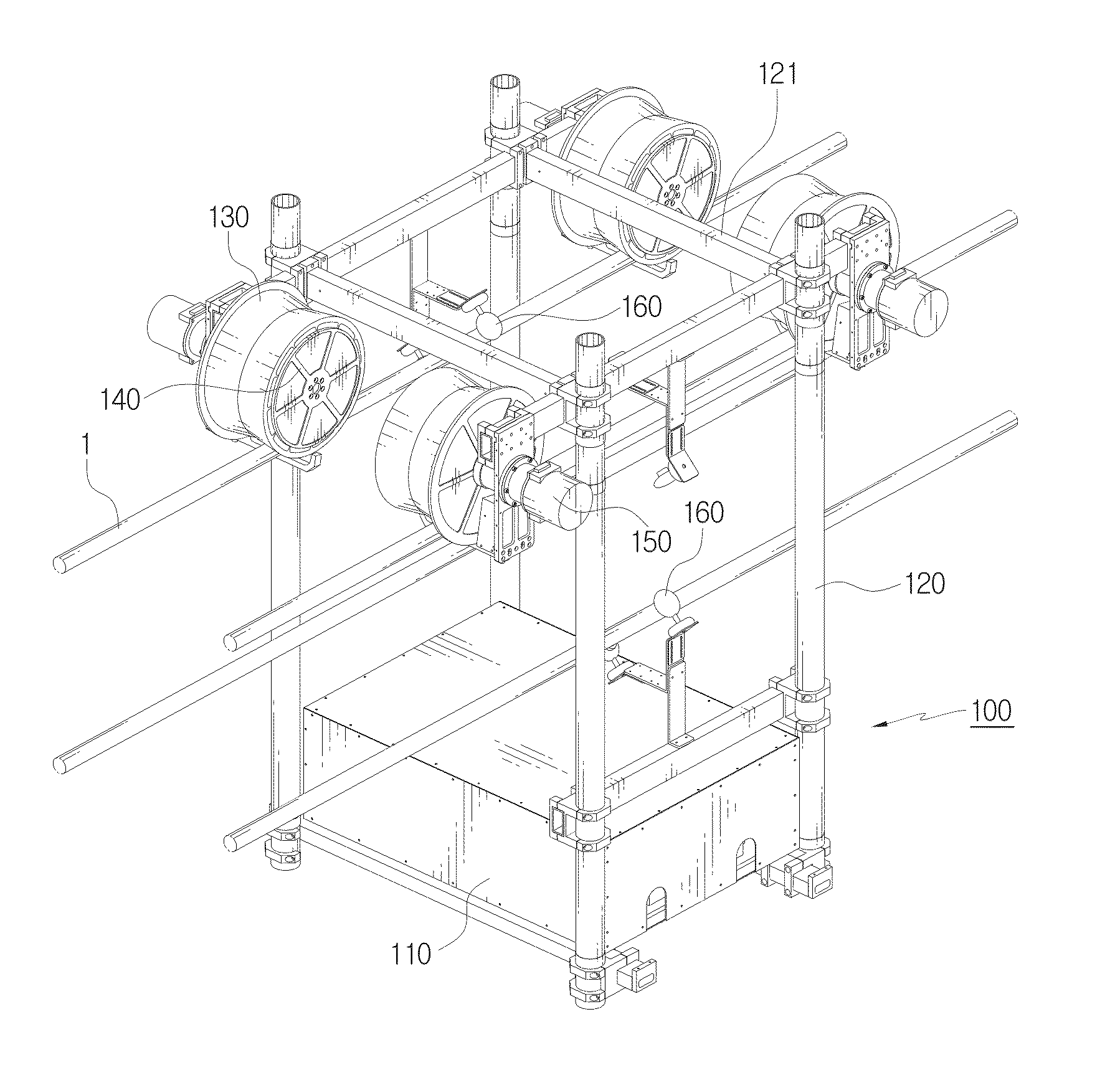
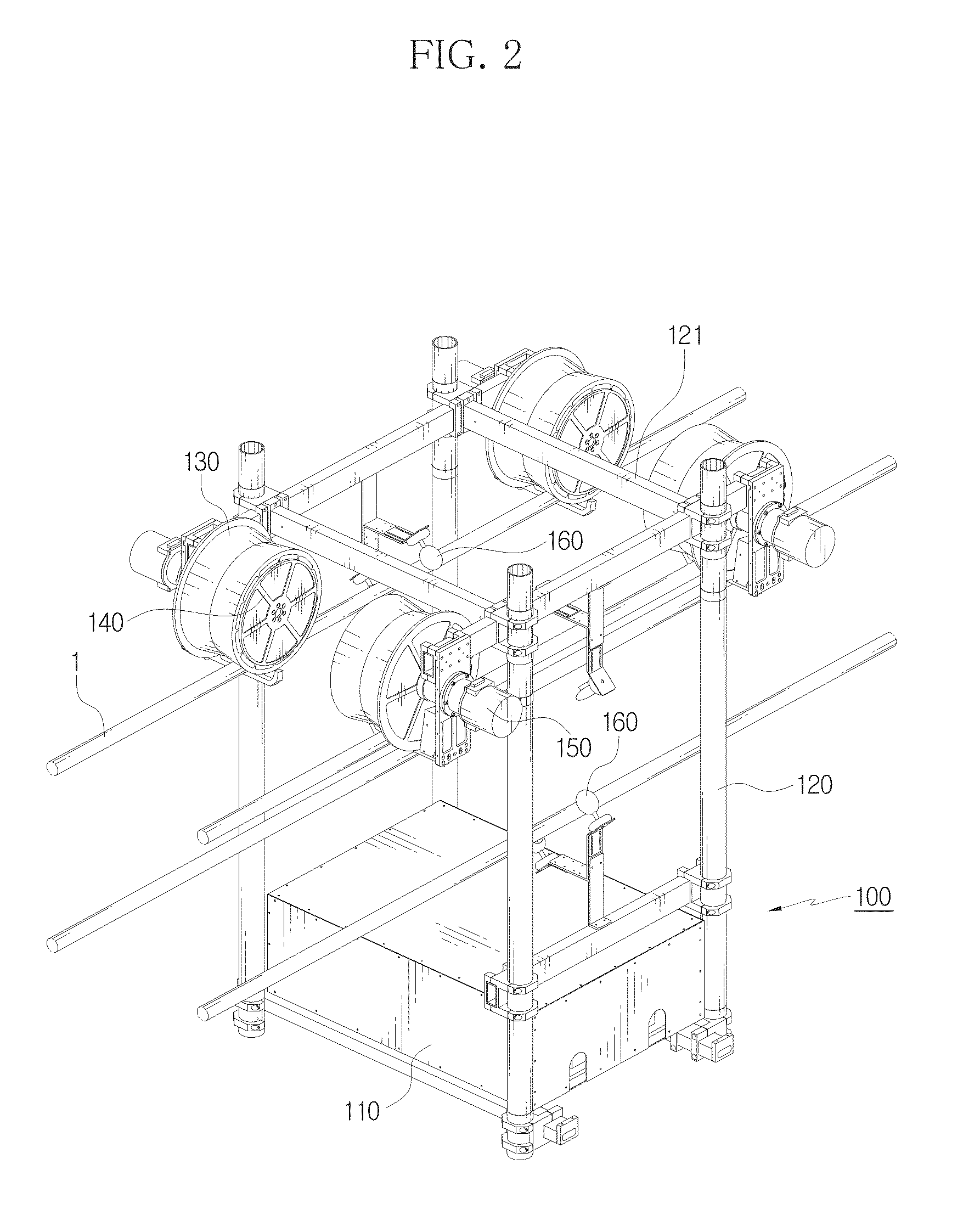
[0033]FIG. 2 illustrates a transmission line inspection robot 100 according to an exemplary embodiment.

[0034]Referring to FIG. 2, the transmission line inspection robot 100 according to this embodiment moves on a 4 conductor transmission line 1. The 4 conductor transmission line 1 is formed of a four stranded wire, and generally, the four stranded wire has a square array when ...


PUM


Abstract

A driving wheel of a robot moving along a wire includes an inner wheel in which a rotation axis being driven to rotate by a motor is fitted, an outer wheel formed to surround the inner wheel and seated on the wire, and a shock absorbing support to elastically connect and support the inner wheel and the outer wheel between the inner wheel and the outer wheel, and a shock being transmitted is absorbed by allowing a relative movement of the inner wheel and the outer wheel by the elastic movement of the shock absorbing support. A robot moving includes a robot body, the driving wheel, a motor to drive the driving wheel by rotating the rotation axis, a connecting arm to connect and support the driving wheel and the robot body.

Description

CROSS-REFERENCE TO RELATED APPLICATION[0001]This application claims priority to Korean Patent Application No. 10-2013-0009848, filed on Jan. 29, 2013, and all the benefits accruing therefrom under 35 U.S.C. §119, the contents of which in its entirety are herein incorporated by reference.BACKGROUND[0002]1. Field[0003]The present disclosure relates to a driving wheel of a robot moving along a wire and a robot having the same, and more particularly, to a driving wheel of a robot moving in orbit along an elongated wire such as a transmission line and a robot having the same.[0004]2. Description of the Related Art[0005]With the development of industries, use of electricity is increasing. To meet the fast growing demand for electric power, power generation plants and transmission lines are continuously being built. Along with this, there is a trend toward emphasizing the significance of inspection and maintenance tasks of a transmission line specialized to carry electricity generated from...

Claims


Application Information

Patent Timeline
Patent Type & Authority Applications(United States)
IPC IPC(8): H02G1/02B61B3/02B60B17/00
CPCH02G1/02B60B17/0089Y10S901/01Y10S901/44B61B3/02B60B5/02B60B9/26B60B17/0027B60B17/0072B60B17/0093B60B2900/325B25J5/02
Inventor JUNG, BYEONG INKIM, CHANG HWANLEE, TAIKJINKIM, JAE HUNLEE, SEOKPARK, SUNG KEE
Owner KOREA INST OF SCI & TECH
Learn More