
Semiconductor device comprising metallization layers of reduced interlayer capacitance by reducing the amount of etch stop materials

Inactive Publication Date: 2014-07-17
GLOBALFOUNDRIES INC
View PDF1 Cites 0 Cited by
  • Summary
  • Abstract
  • Description
  • Claims
  • Application Information

AI Technical Summary

Benefits of technology

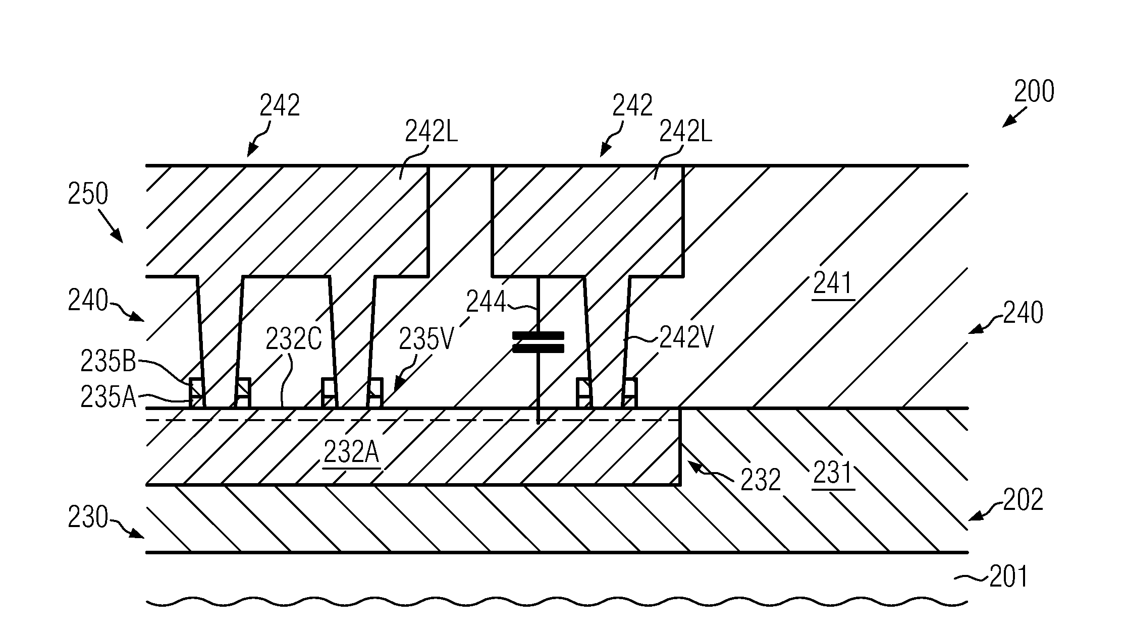
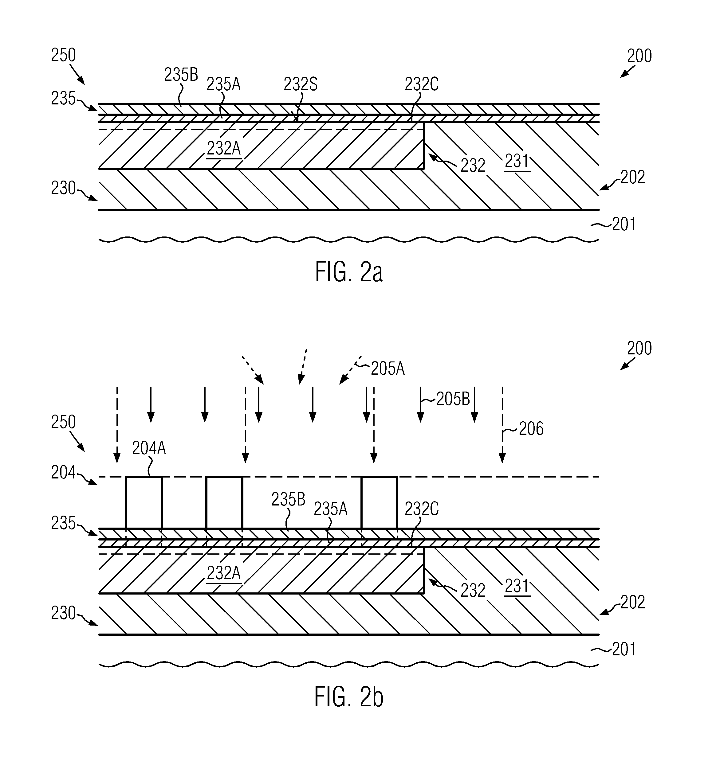
The present patent provides a way to make semiconductor devices by patterning the material of a metallization layer using an etch stop material. This material helps to create via openings but doesn't contribute to the overall capacitance of the whole system. The etch stop material is applied in a very specific way to avoid areas that are important for capacitance. By using this method, the via openings can be patterned reliably without being affected by the etch stop material. This results in better accuracy and efficiency in the manufacturing process.

Problems solved by technology

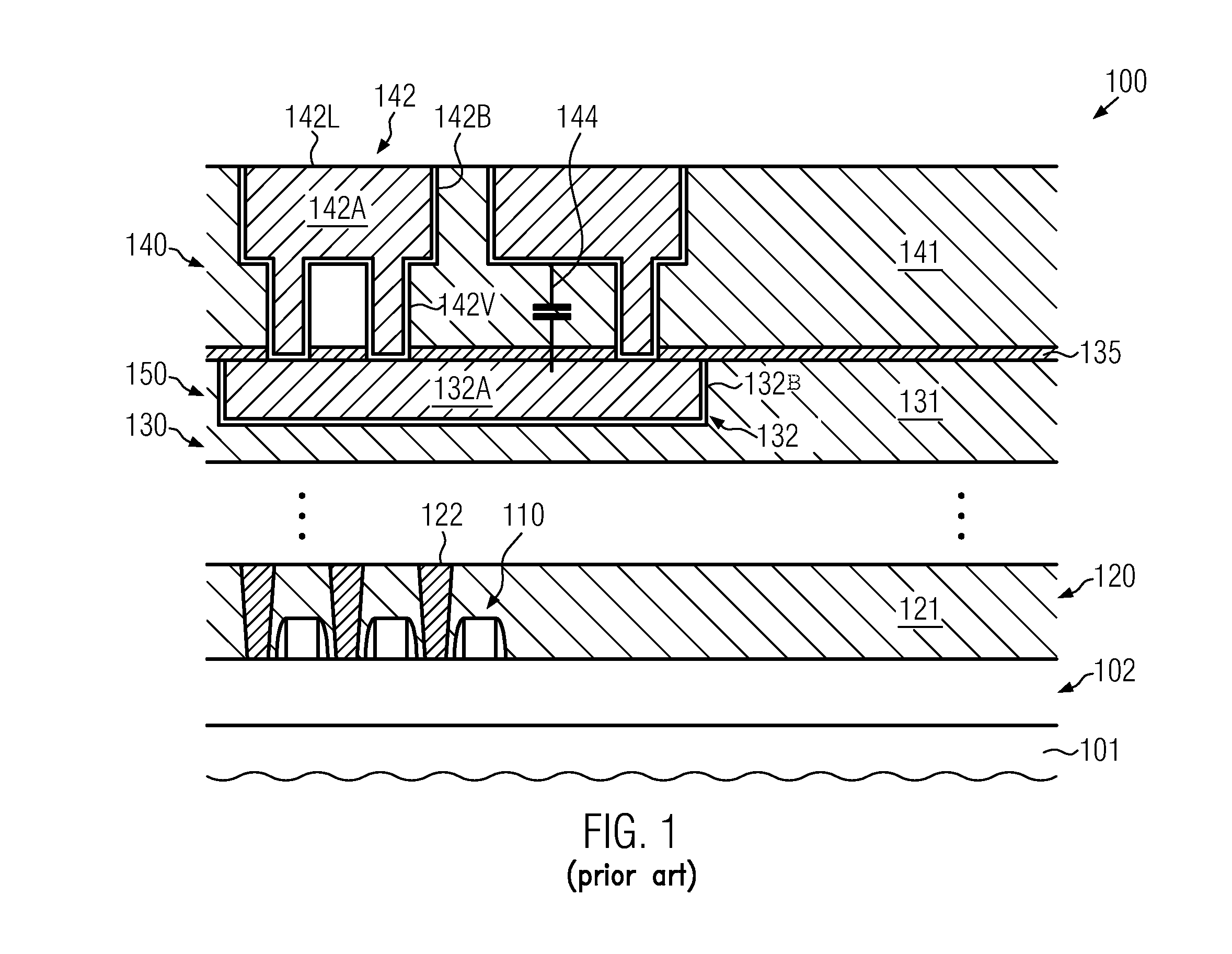
Since the layer 135 has to provide sufficient etch stop capabilities, possibly in combination with cap layer capabilities for providing superior electromigration behavior of the metal line 132, it is very difficult to find appropriate materials with reduced dielectric constant, while also a significant reduction in overall thickness is less than desirable, in particular in view of the etch control capabilities required for patterning the dielectric material 141.
For this reason, frequently, the dielectric constant of the material 141 is further reduced, for instance by incorporating ULK materials, which, however, may exhibit a significantly reduced mechanical and chemical stability.
It has been observed, however, that a further reduction of the dielectric constant of the material 141 may result in significant instabilities of the metallization system 150, while also increased etch damage may occur upon patterning the material 141, which may result in a compensation or even an increase of the finally obtained dielectric constant.

Method used


Image

  • Semiconductor device comprising metallization layers of reduced interlayer capacitance by reducing the amount of etch stop materials
  • Semiconductor device comprising metallization layers of reduced interlayer capacitance by reducing the amount of etch stop materials
  • Semiconductor device comprising metallization layers of reduced interlayer capacitance by reducing the amount of etch stop materials

Examples


Embodiment Construction

[0028]Various illustrative embodiments of the invention are described below. In the interest of clarity, not all features of an actual implementation are described in this specification. It will of course be appreciated that in the development of any such actual embodiment, numerous implementation-specific decisions must be made to achieve the developers' specific goals, such as compliance with system-related and business-related constraints, which will vary from one implementation to another. Moreover, it will be appreciated that such a development effort might be complex and time-consuming, but would nevertheless be a routine undertaking for those of ordinary skill in the art having the benefit of this disclosure.

[0029]The present subject matter will now be described with reference to the attached figures. Various structures, systems and devices are schematically depicted in the drawings for purposes of explanation only and so as to not obscure the present disclosure with details ...


PUM


Abstract

Upon forming a complex metallization system, the parasitic capacitance between metal lines of adjacent metallization layers may be reduced by providing a patterned etch stop material. In this manner, the patterning process for forming the via openings may be controlled in a highly reliable manner, while, on the other hand, the resulting overall dielectric constant of the metallization system may be reduced, thereby also significantly reducing the parasitic capacitance between stacked metal lines.

Description

BACKGROUND OF THE INVENTION[0001]1. Field of the Invention[0002]Generally, the present disclosure relates to microstructures, such as advanced integrated circuits, and, more particularly, to conductive structures, such as copper-based metallization layers, comprising metal lines and vias.[0003]2. Description of the Related Art[0004]In the fabrication of modem microstructures, such as integrated circuits, there is a continuous drive to steadily reduce the feature sizes of microstructure elements, thereby enhancing the functionality of these structures. For instance, in modern integrated circuits, minimum feature sizes, such as the channel length of field effect transistors, have reached the deep sub-micron range, thereby increasing performance of these circuits in terms of speed and / or power consumption and / or diversity of functions. As the size of individual circuit elements is reduced with every new circuit generation, thereby improving, for example, the switching speed of the tran...

Claims


Application Information

Patent Timeline
IPC IPC(8): H01L23/48
CPCH01L23/481H01L2924/0002H01L23/5222H01L23/53295H01L21/76807H01L21/76832H01L21/76834H01L2924/00
Inventor HEINRICH, JENSHUISINGA, TORSTENRICHTER, RALFPFUETZNER, RONNY
Owner GLOBALFOUNDRIES INC
Learn More