
Camera for generating a biometrical signal of a living being

a technology of living beings and cameras, applied in the field of cameras for generating biometric signals of living beings, to achieve the effect of less complex and expensiv

Active Publication Date: 2014-07-10
KONINKLIJKE PHILIPS ELECTRONICS NV
View PDF10 Cites 63 Cited by
  • Summary
  • Abstract
  • Description
  • Claims
  • Application Information

AI Technical Summary

Benefits of technology

The present invention provides a camera and method for generating a biometrical signal of a living being that can be used in a wider range of applications and at a lower cost compared to conventional equipment. The camera has a color sensor that generates multiple color signals, which are combined to create an optimized color signal for biometrical signal detection. The combination unit minimizes cross-talk between the color signals to maximize the contrast of the resulting biometrical signal. Using multiple PPG signals at different wavelengths and maximizing the difference of normalized amplitudes helps to improve heart rate calculation and eliminate distortions in the signals.

Problems solved by technology

Camera-based SpO2 monitoring is conventionally realized by two monochrome cameras with corresponding optical band-pass filters, but this is non-practical due to the required alignment (i.e. spatial alignment of the images from two or more sensors), complexity and costs for many applications, such as applications in sports, home-use or for implementation in smart devices, such as mobile phones.

Method used


Image

  • Camera for generating a biometrical signal of a living being
  • Camera for generating a biometrical signal of a living being
  • Camera for generating a biometrical signal of a living being

Examples


first embodiment

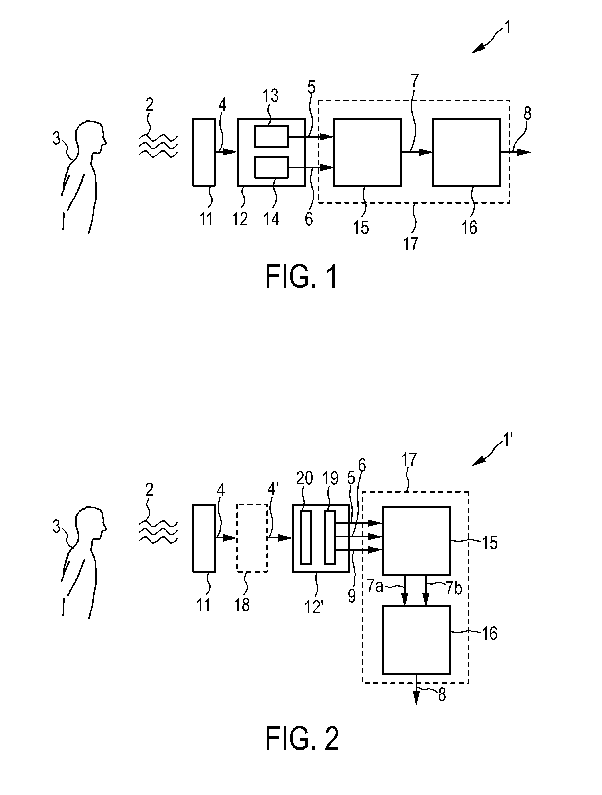
[0046]FIG. 1 shows a schematic diagram of a camera 1 according to the present invention. Electromagnetic radiation 2, in particular light in the visible and infrared wavelength range, reflected from a living being 3, such as a patient, is received and evaluated by said camera 1 for finally generating the biometrical signal of the living being 3. The camera comprises a filter 11 for blocking incident visible light within the incident electromagnetic radiation 2 in a wavelength range up to at least substantially 550 nm, preferably up to approximately 600 nm, even more preferably up to 650 nm. The filtered incident light 4 is then sensed by a color sensor 12 that generates at least two different color signals 5, 6, e.g. by use of two separate color detectors 13, 14 (or an array of such color detectors). A combination unit 15 generates at least one combined color signal 7 by combining said color signals 5, 6, e.g. by a linear combination. Finally, a processing unit 16 is provided for pr...

second embodiment

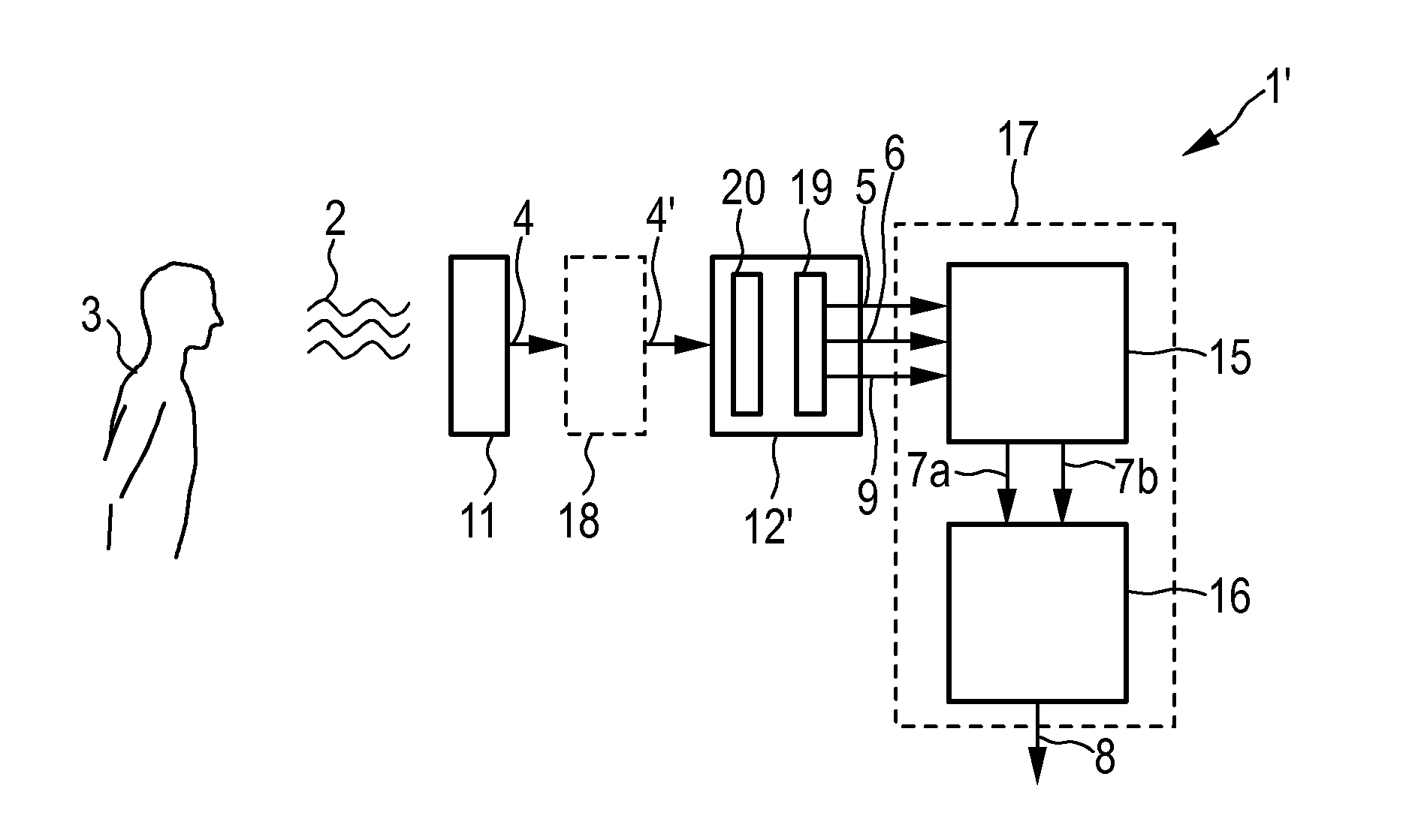
[0048]FIG. 2 schematically shows a camera 1′ according to the present invention. FIG. 2 shows that optionally an additional filter 18 may be provided (in this and / or other embodiments), which filter 18 is configured to block incident light in a wavelength range above at least 1100 nm, in particular above at least 1000 nm, before reaching the color sensor 12′. While generally those color sensors, e.g. imaging silicon sensors, show a sensitivity that naturally decreases towards longer wavelengths, such an additional filter 18 ensures that signal contributions within the filtered incident light 4 above said upper threshold wavelength are blocked, i.e. signal contributions in which water absorption becomes dominant are blocked in the twice filtered incident light 4′.

[0049]Further, in this embodiment the color sensor 12′ generates three different color signals 5, 6, 9, e.g. by use of a color filter array 20 having three different color filter areas provided in front of a photo detector 1...


PUM


Abstract

The present invention relates to a camera (1, 1′) for generating a biometrical signal of a living being comprising: a filter (11) for blocking incident visible light in a wavelength range up to at least 550 nm, a color sensor (12, 12′) for receiving said filtered incident light and generating at least two different color signals (5, 6, 9), a combination unit (15) for generating at least one combined color signal (7a, 7b) by combining said at least two color signals, and a processing unit (16) for processing said at least one combined color signal and extracting at least one biometrical signal (8) of said living being (3).

Description

FIELD OF THE INVENTION[0001]The present invention relates to a camera for generating a biometrical signal of a living being. The present invention relates further to a method for generating a biometrical signal of a living being. Still further, the present invention relates to a processor and a processing method for use in such a camera and method. Finally, the present invention relates to a computer program for implementing said processing method.BACKGROUND OF THE INVENTION[0002]Pulse oximetry is a non-invasive method allowing a monitoring of the oxygenation of a patient's hemoglobin using a pulse oximeter. A sensor is placed on a thin part of a patient's body, usually a finger tip or earlobe. Red light with a wavelength around 650 nm and infrared light with a wavelength around 850 to 940 nm are sequentially passed through the patient to a photodetector. The changing absorbance of each of the two wavelengths is measured, allowing determination of the absorbances due to the pulsing ...

Claims


Application Information

Patent Timeline
Patent Type & Authority Applications(United States)
IPC IPC(8): G06T7/00A61B5/1455A61B5/024
CPCG06T7/0012A61B5/14551A61B5/02427G06T7/0016G06T2207/10024G06T2207/30076
Inventor BARTULA, MAREK JANUSZVERKRUIJSSE, WILLEM
Owner KONINKLIJKE PHILIPS ELECTRONICS NV
Learn More