
Lens apparatus and image pickup apparatus including the same

a technology of image pickup and lens, which is applied in the field of lens apparatus having an image stabilization function, can solve the problems of deterioration of optical performance, decreased conspicuous decrease in peripheral light amount, so as to achieve high peripheral light amount ratio, high optical performance, and large vibration isolation

Inactive Publication Date: 2014-07-03
CANON KK
View PDF7 Cites 5 Cited by
  • Summary
  • Abstract
  • Description
  • Claims
  • Application Information

AI Technical Summary

Benefits of technology

The present invention provides a lens apparatus with high optical performance and a high peripheral light amount ratio in large vibration isolation. The lens includes a light-weight movable lens unit and a small entire optical system. The invention also provides an image pickup apparatus that utilizes this lens.

Problems solved by technology

H09-251127 has a problem in that optical performance is deteriorated when the image stabilization is performed because a rotation angle of the first lens unit is increased.
In addition, the method of Japanese Patent Application Laid-Open No. 2003-202499 has a problem in that a light beam is vignetted so that a peripheral light amount ratio is decreased because the shift and the rotation are performed by two lens units in vicinity or in a rear side of an aperture stop.
Therefore, because it is necessary to increase the movement component in the perpendicular direction for performing large vibration isolation, the deterioration of the optical performance and the decrease in peripheral light amount become conspicuous.
However, a large actuator is necessary for driving the lens unit because the part to be moved has a large weight, which results in an increase of weight.

Method used


Image

  • Lens apparatus and image pickup apparatus including the same
  • Lens apparatus and image pickup apparatus including the same
  • Lens apparatus and image pickup apparatus including the same

Examples


embodiment 1

[0064]Hereinafter, details of the present invention are described with reference to embodiments.

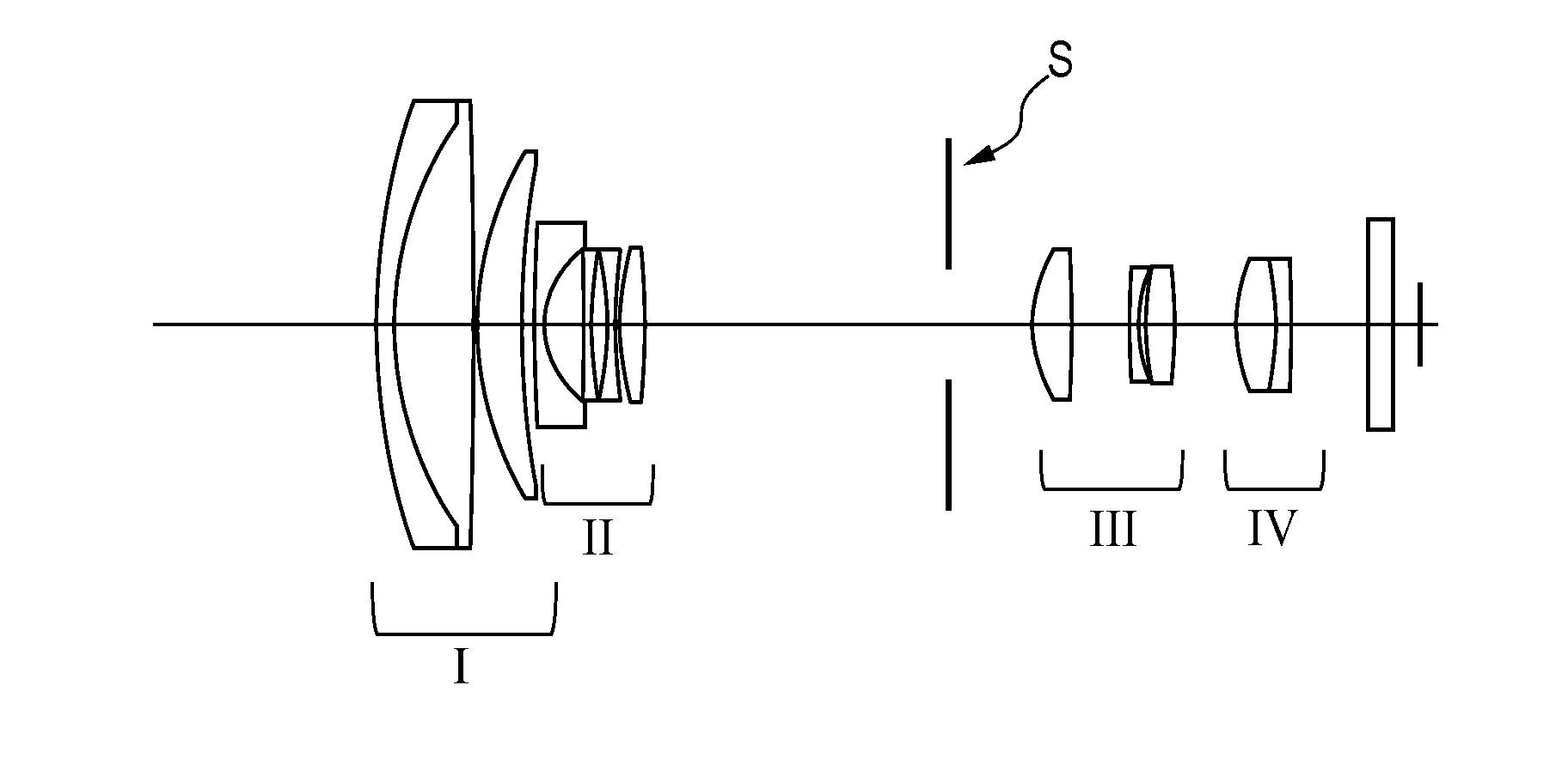
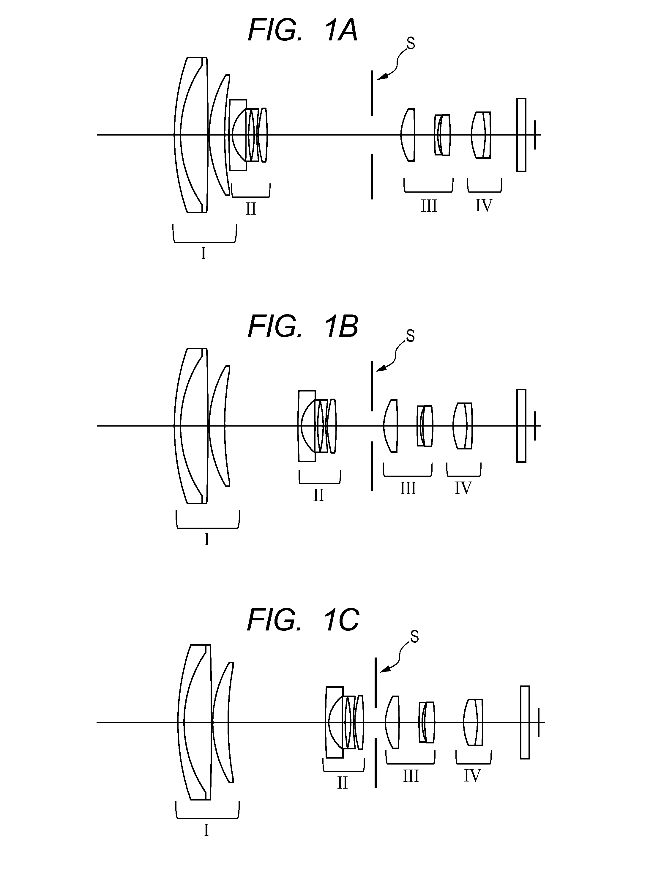
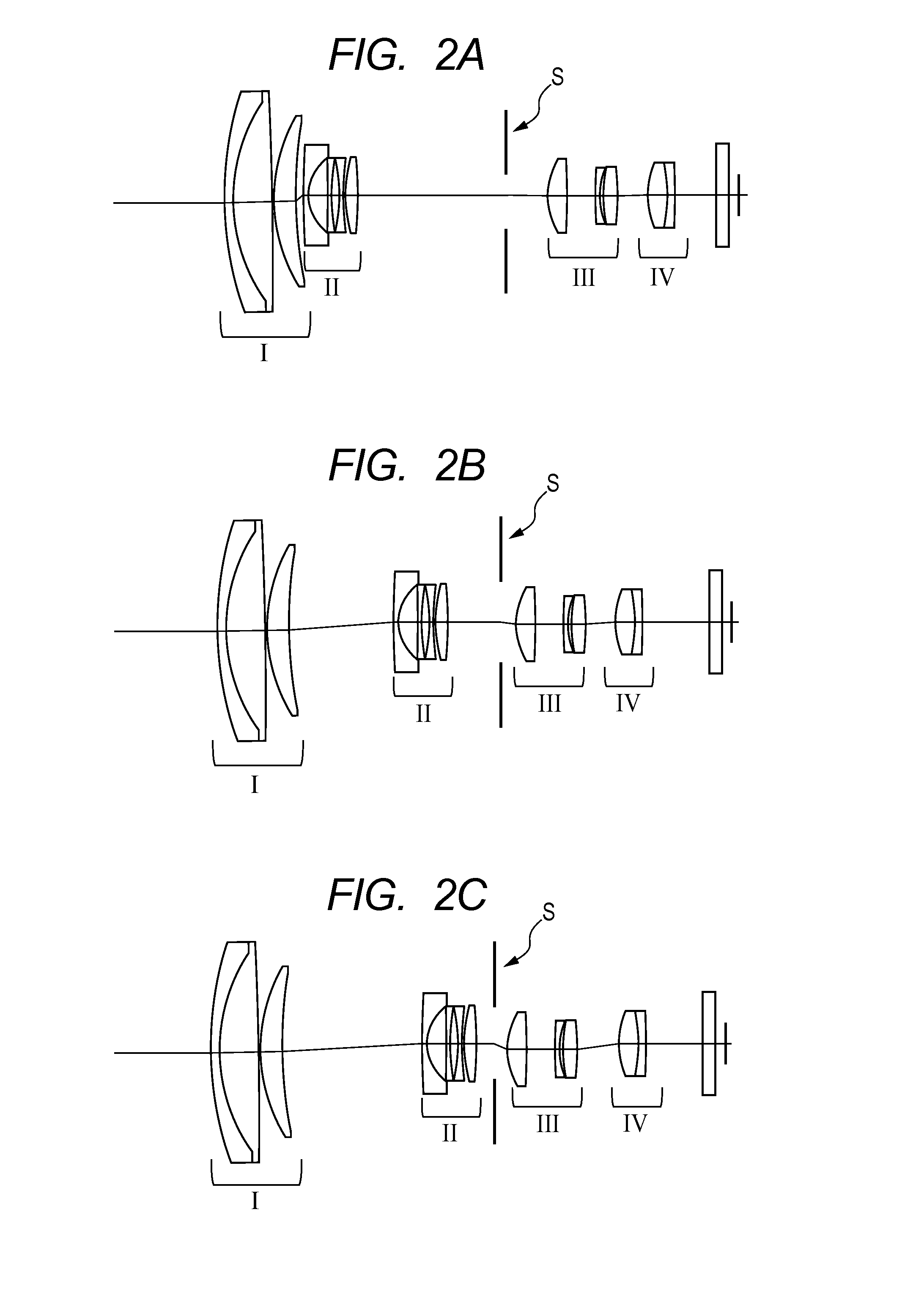
[0065]FIGS. 1A, 1B, 1C, 2A, 2B, and 2C illustrate cross-sectional views of an optical system of a lens apparatus according to Embodiment 1 of the present invention. The lens apparatus of this embodiment includes, in order from an object side, a first lens unit I having a positive refractive power, a second lens unit II having a negative refractive power, a stop (lens stop) S, a third lens unit III having a positive refractive power, and a fourth lens unit IV having a positive refractive power. In addition, the lens apparatus of this embodiment is a zooming optical system in which an interval between the first lens unit I and the second lens unit II, an interval between the second lens unit II and the third lens unit III, and an interval between the third lens unit III and the fourth lens unit IV are changed during zooming.

[0066]FIGS. 1A, 1B, and 1C illustrate cross-sectional views before ...

embodiment 2

[0083]FIGS. 6A, 6B, and 6C are cross-sectional views of a lens apparatus according to Embodiment 2 of the present invention and illustrate cross-sectional views after vibration isolation at the wide angle end (FIG. 6A), at the intermediate focal length (FIG. 6B), and at the telephoto end (FIG. 6C). The lens apparatus includes, in order from the object side, a first lens unit I having a negative refractive power, a stop (lens stop) S, a second lens unit II having a positive refractive power, and a third lens unit III having a positive refractive power. In addition, in the lens apparatus, an interval between the first lens unit I and the second lens unit II as well as an interval between the second lens unit II and the third lens unit III is changed during zooming.

[0084]FIGS. 7A, 7B, and 7C are lateral aberration diagrams illustrating performance of the lens apparatus of Embodiment 2 after vibration isolation. FIGS. 7A, 7B, and 7C illustrate lateral aberration diagrams after vibration...

embodiment 3

[0088]FIGS. 8A, 8B, and 8C are cross-sectional views of a lens apparatus according to Embodiment 3 of the present invention and illustrate cross-sectional views after vibration isolation at the wide angle end (FIG. 8A), at the intermediate focal length (FIG. 8B), and at the telephoto end (FIG. 8C). The lens apparatus includes, in order from the object side, a first lens unit I having a positive refractive power, a second lens unit II having a negative refractive power, a stop (lens stop) S, a third lens unit III having a positive refractive power, a fourth lens unit IV having a negative refractive power, and a fifth lens unit V having a positive refractive power. In addition, in the lens apparatus, an interval between the first lens unit I and the second lens unit II, an interval between the second lens unit II and the third lens unit III, an interval between the third lens unit III and the fourth lens unit IV, and an interval between the fourth lens unit IV and the fifth lens unit ...


PUM


Abstract

A lens apparatus includes an optical system including multiple lens units, the optical system including: a first lens unit which is disposed closest to an object side in the optical system and is rotatable about a point in a vicinity of an optical axis of the optical system; and at least one lens unit which is movable in a direction including a component in a direction perpendicular to the optical axis. The following conditional expression is satisfied: 1.0<ft / |f1|<2.2, where ft represents a focal length of the optical system at a telephoto end, and f1 represents a focal length of the first lens unit. At least one of rotation of the first lens unit or movement of the at least one lens unit in the direction including the component in the direction perpendicular to the optical axis changes an image formation position in the direction perpendicular to the optical axis.

Description

BACKGROUND OF THE INVENTION[0001]1. Field of the Invention[0002]The present invention relates to a lens apparatus having a image stabilization function, and more particularly, to a lens apparatus having a zooming function for a video camera, a silver-halide camera, a digital still camera, and the like, and to an image pickup apparatus including the lens apparatus.[0003]2. Description of the Related Art[0004]Heretofore, an image pickup apparatus such as a video camera is required to have an image stabilization function for preventing image blur due to a shake or the like, and various types of image stabilization methods are proposed. Among them, optical image stabilization, which has an image stabilization function by shifting a single lens or multiple lens units so as to have a component in a direction perpendicular to the optical axis, is widely used at present in a digital still camera, a video camera, and the like.[0005]In addition, other than the above-mentioned image stabilizat...

Claims


Application Information

Patent Timeline
Patent Type & Authority Applications(United States)
IPC IPC(8): H04N5/232H04N5/225G02B9/00
CPCH04N5/23287H04N5/2254G02B9/00G02B27/646G02B15/144113G02B15/143507G03B2207/005G02B13/009H04N23/687H04N23/682H04N23/685
Inventor KAWAMURA, JUN
Owner CANON KK
Learn More