
Welding Process for the Welding of Aluminum

a welding process and aluminum technology, applied in the direction of soldering devices, manufacturing tools,auxillary welding devices, etc., can solve the problems of affecting the welding process, affecting the welding, and affecting the welding, so as to achieve the effect of welded particularly easily and inexpensively

Active Publication Date: 2014-07-03
ROBERT BOSCH GMBH
View PDF5 Cites 14 Cited by
  • Summary
  • Abstract
  • Description
  • Claims
  • Application Information

AI Technical Summary

Benefits of technology

The patent describes a welding process where the welding time is extended to improve the quality of welding points. The control of the welding process is based on the force between the welding electrodes measured by a force sensor. The quality of the welding points is measured based on the force between the electrodes. By extending the welding time and monitoring the force, the quality of the welding points can be improved. This welding process is efficient, easy, and inexpensive, and is particularly useful for welding aluminum. Additionally, the patent describes a method for detecting welding spatter and compensating for energy loss caused by spatter.

Problems solved by technology

Such welding processes that are already known cannot however be applied to the special needs of the welding of aluminum.
, which envelops the aluminum parts to be welded together and hinders the welding. I
n other words, such welding processes that are designed for the welding of steel but are used for the welding of aluminum lead to welding points of low quality, and to this extent have for example inadequate strength and / or structural damage.

Method used


Image

  • Welding Process for the Welding of Aluminum
  • Welding Process for the Welding of Aluminum
  • Welding Process for the Welding of Aluminum

Examples


Embodiment Construction

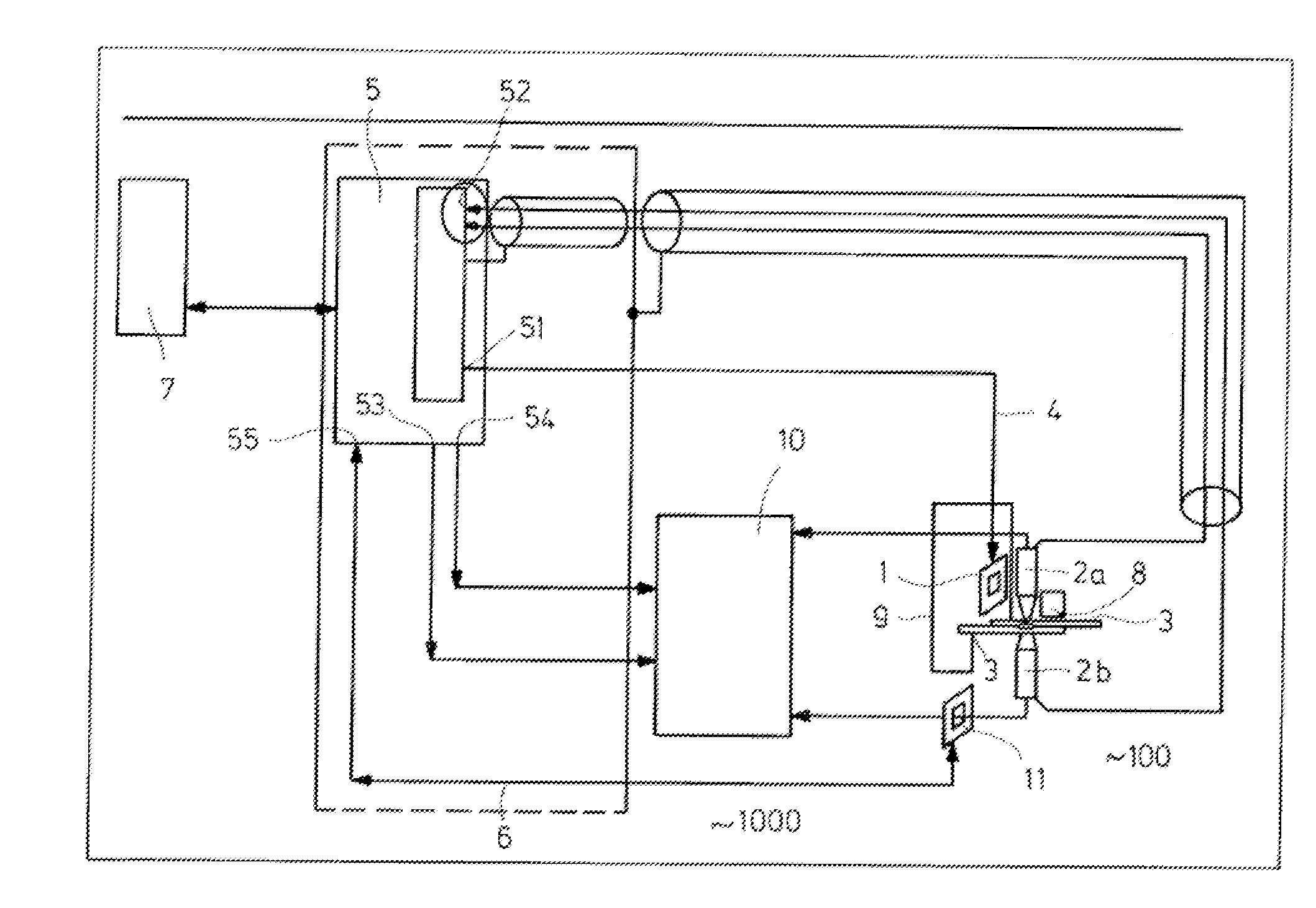
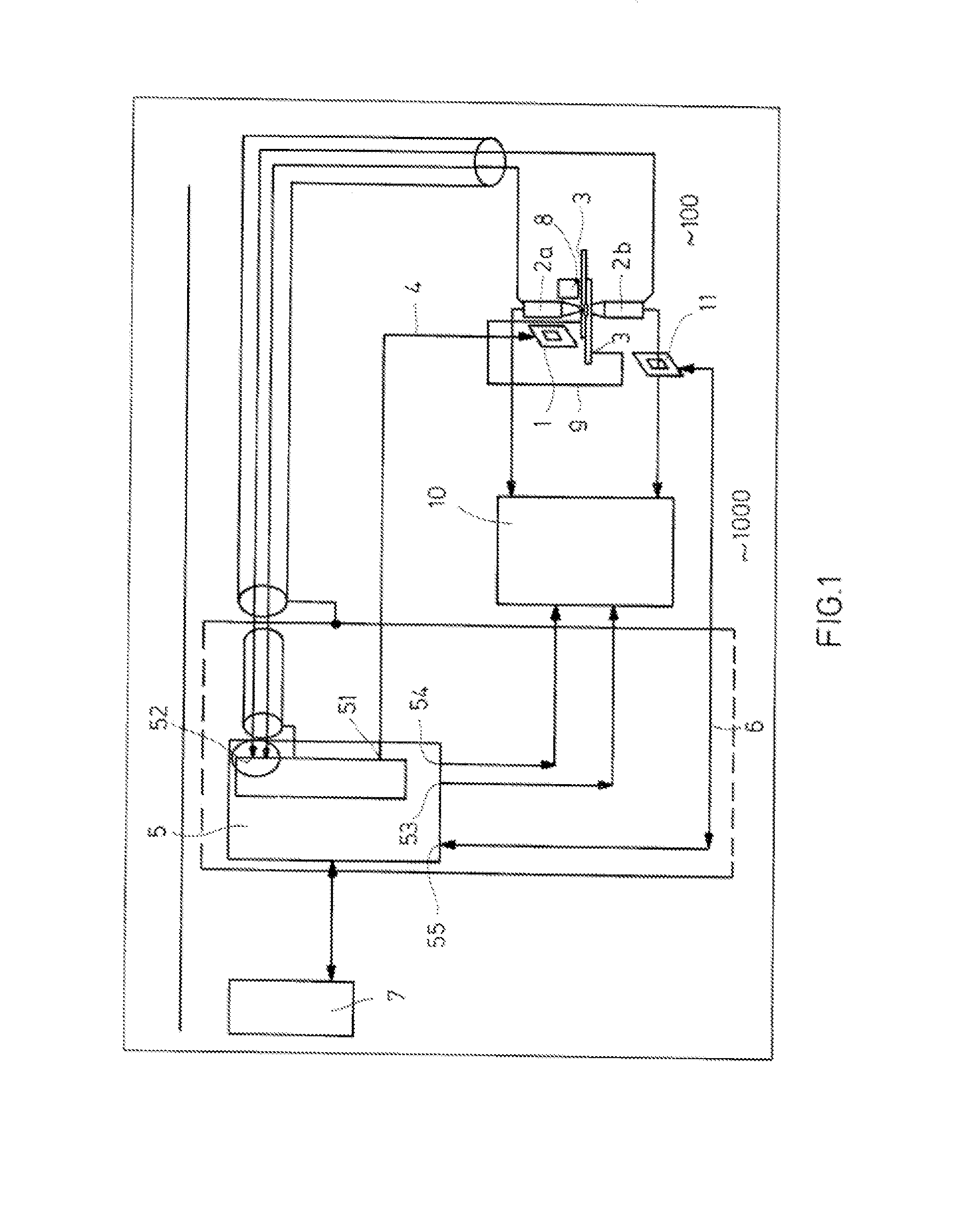
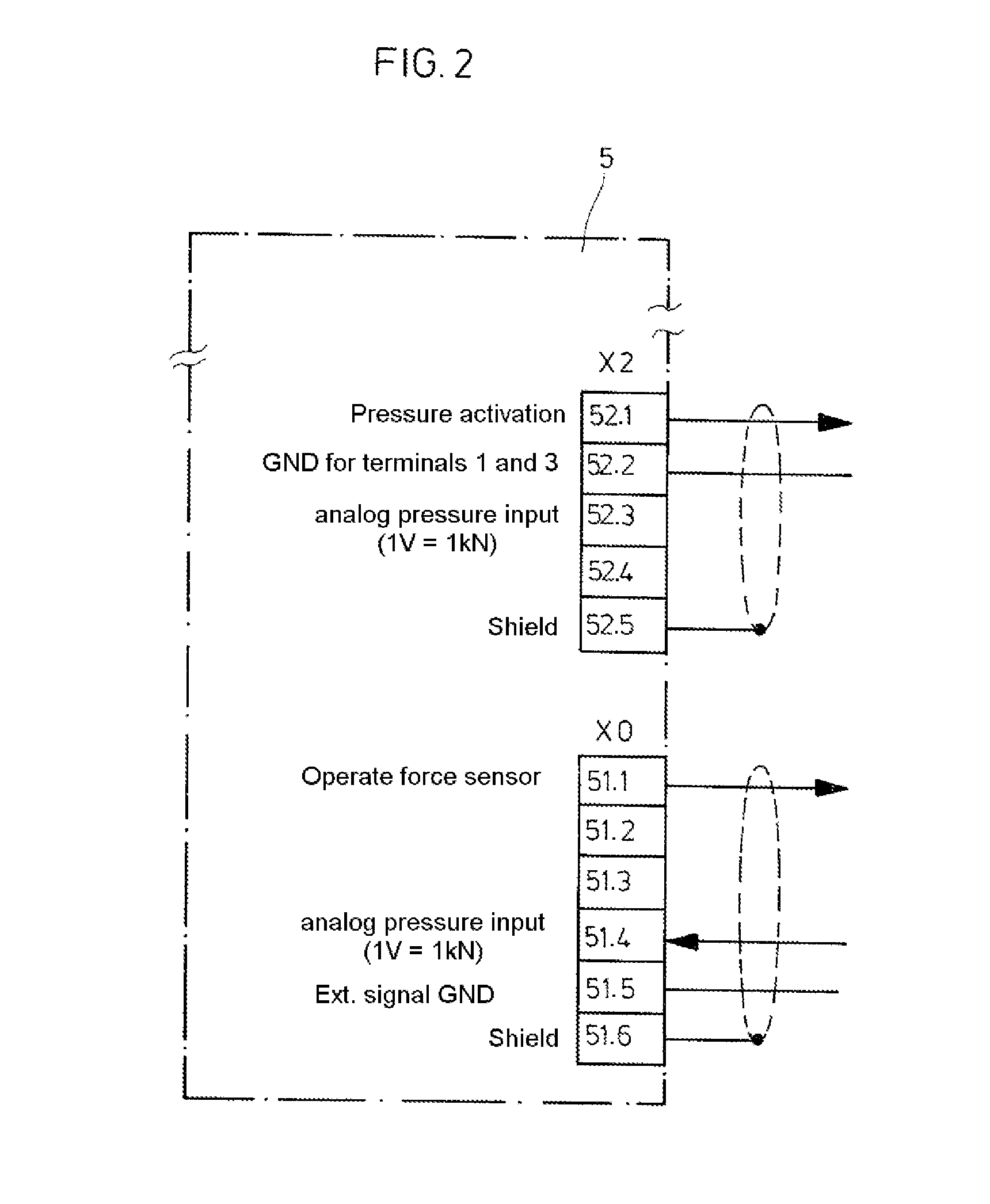
[0023]The welding device 1000 represented in FIG. 1 for the welding of aluminum comprises a force sensor 1, by means of which a force between two welding electrodes 2a, 2b on aluminum elements 3 to be welded can be measured and by means of which the measured force values can be transmitted to a welding control 5.

[0024]Moreover, up to the elapse of a set welding time, the welding control 5 is used to calculate in each case during and / or after the elapse of predeterminable incremental time frames at least one absolute value and / or at least one increase in the measured force and respectively store it, wherein it is possible by means of the welding control 5 to compare the measured absolute value and / or the increase in the measured force in each case with a reference value and / or a reference curve and to calculate a control deviation resulting from the comparison.

[0025]In particular, the welding control is provided and designed such that, after the elapse of the set welding time, it sub...


PUM

PropertyMeasurementUnit
timeaaaaaaaaaa
timeaaaaaaaaaa
timeaaaaaaaaaa

Abstract

A welding process for the welding of aluminium includes a force sensor measuring a force between two welding electrodes on aluminum elements to be welded and transmitting its measured values to a welding control. Until the elapse of a set welding time, the welding control calculates and stores at least one absolute value and / or at least one increase in the measured force. The welding control compares the measured absolute value and / or the increase in the measured force with a reference value and / or a reference curve and calculates a control deviation from the comparison. After the elapse of the set welding time, the welding control subjects the welding electrodes to a constant current during a welding time extension that follows the set welding time, dependent on a magnitude of the control deviation that is measured at the point in time of the elapse and / or during the set welding time.

Description

[0001]This application claims priority under 35 U.S.C. §119 to patent application no. DE 10 2012 025 200.5 filed on Dec. 27, 2012 in Germany, the disclosure of which is incorporated herein by reference in its entirety.BACKGROUND [0002]The disclosure relates to a welding process for the welding of aluminum, in which at least one force sensor measures a force between two welding electrodes on aluminum elements to be welded and transmits its measured values to a welding control. Up to the elapse of a set welding time, the welding control thereby calculates in each case during and / or after the elapse of predeterminable incremental time frames at least one absolute value and / or at least one increase in the measured force and stores it, the welding control comparing the measured absolute value and / or the increase in the measured force in each case with a reference value and / or a reference curve and calculating a control deviation resulting from the comparison.[0003]Welding processes of th...

Claims


Application Information

Patent Timeline
Patent Type & Authority Applications(United States)
IPC IPC(8): B23K11/25B23K11/31
CPCB23K11/31B23K11/255B23K11/115B23K11/185
Inventor ARNDT, VOLKERHAEUFGLOECKNER, JUERGENRIPPER, MICHAEL
Owner ROBERT BOSCH GMBH
Learn More