
Automatic bonding system for liquid crystal display device and automatic bonding method using the same

a liquid crystal display and automatic bonding technology, which is applied in the field of automatic bonding system for liquid crystal display devices and automatic bonding methods using the same, can solve the problems of reducing the hardening rate of adhesive resin, affecting the appearance quality of liquid crystal displays, and limiting the color of images displayed by liquid crystal displays. , to achieve the effect of enhancing the hardening rate and reducing air bubbles

Active Publication Date: 2014-07-03
LG DISPLAY CO LTD
View PDF9 Cites 7 Cited by
  • Summary
  • Abstract
  • Description
  • Claims
  • Application Information

AI Technical Summary

Benefits of technology

The present invention provides a touch panel type LCD device with high-quality screen, various design colors, and enhanced intensity. Additionally, an automatic bonding system and method are provided for quickly and accurately bonding a touch panel to a liquid crystal panel, thus improving productivity and quality of products. The bonding unit includes a gap dispenser to reduce air bubbles, and the pre-hardening unit includes a UV LED to enhance hardening rate of adhesive resin.

Problems solved by technology

Elements stacked on the liquid crystal panel fundamentally use a colorless transparent material, but as the number of stacked elements increases, there is a limitation in maintaining a color of an image displayed by the liquid crystal panel.
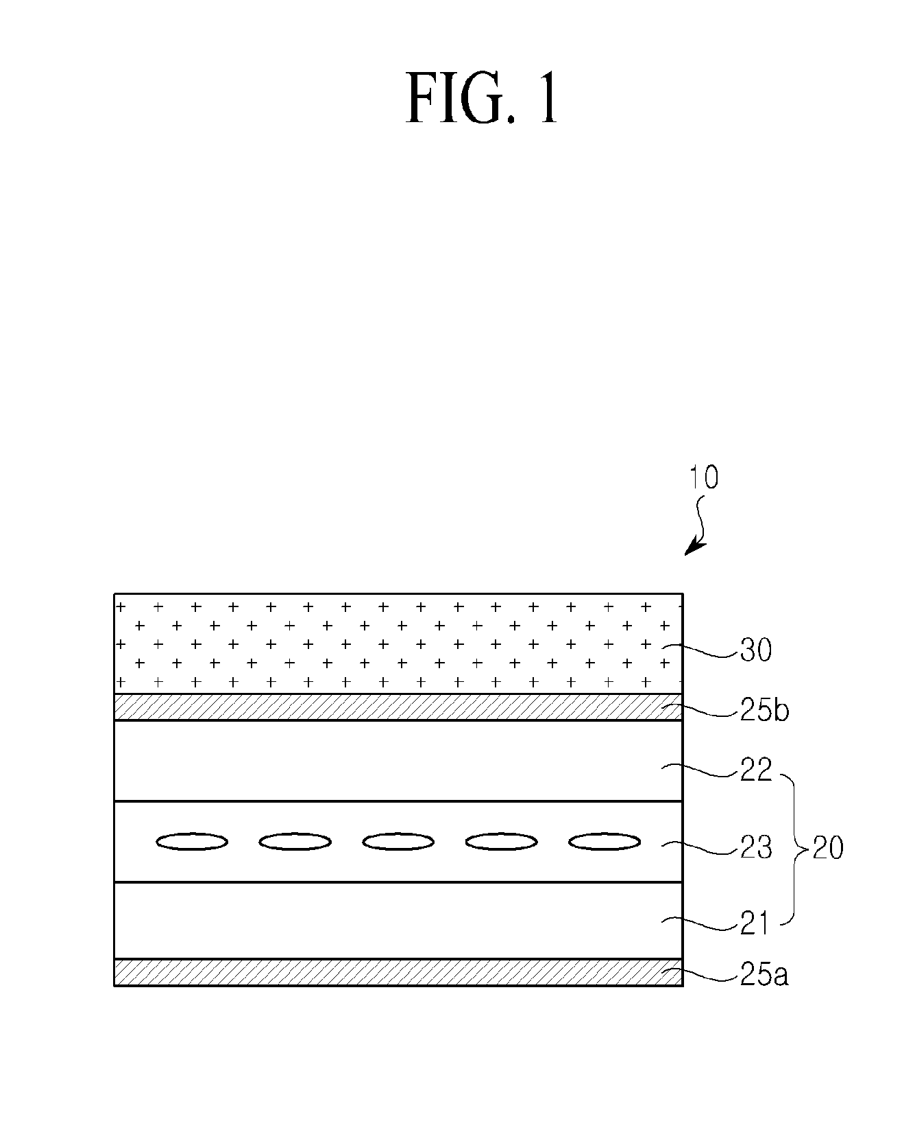
However, even in this case, since an air gap is formed between the touch panel and the liquid crystal panel, light is scattered due to a high optical refractive index deviation between the air gap and the liquid crystal panel to cause a degradation in a quality of an image, and structural intensity is weakened by the air gap.
For this reason, the touch panel is easily damaged by external force.

Method used


Image

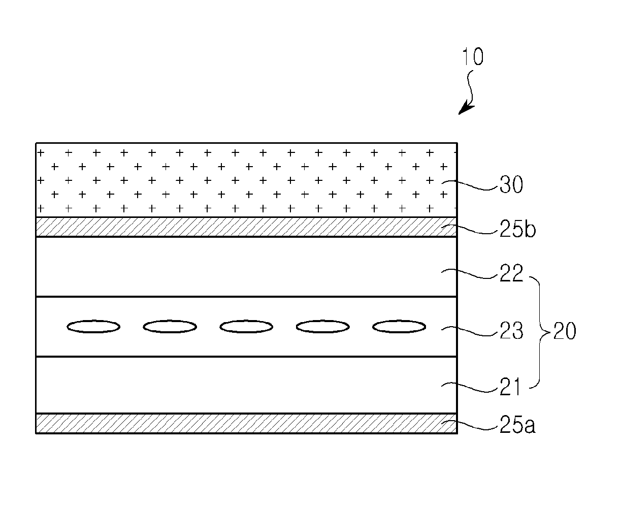
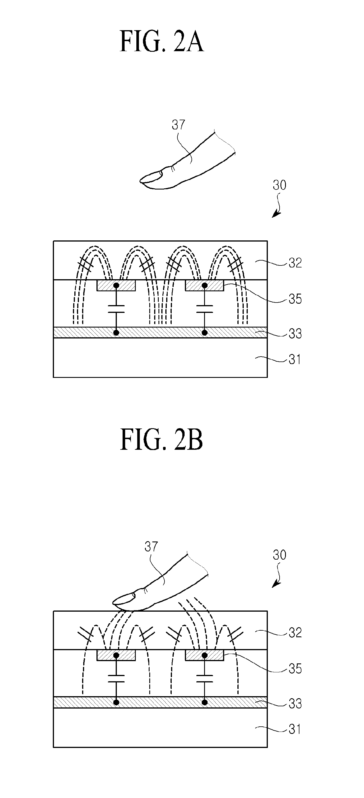
  • Automatic bonding system for liquid crystal display device and automatic bonding method using the same
  • Automatic bonding system for liquid crystal display device and automatic bonding method using the same
  • Automatic bonding system for liquid crystal display device and automatic bonding method using the same

Examples


Embodiment Construction

[0036]Reference will now be made in detail to the exemplary embodiments of the present invention, examples of which are illustrated in the accompanying drawings. Wherever possible, the same reference numbers will be used throughout the drawings to refer to the same or like parts.

[0037]The terms described in the specification should be understood as follows.

[0038]As used herein, the singular forms “a”, “an” and “the” are intended to include the plural forms as well, unless the context clearly indicates otherwise. The terms “first” and “second” are for differentiating one element from the other element, and these elements should not be limited by these terms.

[0039]It will be further understood that the terms “comprises”, “comprising,”, “has”, “having”, “includes” and / or “including”, when used herein, specify the presence of stated features, integers, steps, operations, elements, and / or components, but do not preclude the presence or addition of one or more other features, integers, st...


PUM

PropertyMeasurementUnit
Sizeaaaaaaaaaa
Surface tensionaaaaaaaaaa

Abstract

Disclosed is an automatic bonding system for an LCD device. The automatic bonding system includes a bonding unit configured to perform a process of bonding a first substrate to a second substrate, a first substrate supply unit configured to include an inverting arm and supply the first substrate to the bonding unit, a second substrate supply unit configured to include an adhesive resin coating unit and supply the second substrate to the bonding unit, a pre-hardening unit configured to perform a process of pre-hardening an adhesive resin that adheres the first and second substrates, and a hardening unit configured to perform a process of hardening the adhesive resin that adheres the first and second substrates. A gap between the first and second substrates bonded to each other by the bonding unit is a bonding gap controlled by a gap variable control stage.

Description

CROSS-REFERENCE TO RELATED APPLICATIONS[0001]This application claims the benefit of the Korean Patent Application No. 10-2012-0158721 filed on Dec. 31, 2012, which is hereby incorporated by reference for all purposes as if fully set forth herein.BACKGROUND OF THE INVENTION[0002]1. Field of the Invention[0003]The present invention relates to an automatic bonding system for a liquid crystal display (LCD) device and an automatic bonding method using the same.[0004]2. Discussion of the Related Art[0005]As society advances to a more information-oriented society, the display field of processing and displaying a massive amount of information is rapidly advancing, and correspondingly, various flat panel display (FPD) devices are developed and are attracting much attention.[0006]Examples of the FPD devices include LCD devices, plasma display panel (PDP) devices, field emission display (FED) devices, electroluminescence display (ELD) devices, etc. Such FPD devices have excellent performance i...

Claims


Application Information

Patent Timeline
IPC IPC(8): G02F1/13
CPCG02F1/1303B32B37/003B32B37/1054B32B37/1284B32B39/00B32B2457/208G02F1/13338Y10T156/1744G02F1/13G02F1/1333
Inventor JUNG, WAN WOOLEE, SEUNG LYULKIM, CHUN ILPARK, CHANG YEOLLEE, SEUNG KIL
Owner LG DISPLAY CO LTD
Learn More