
Tn liquid crystal display device and touch control method thereof

Active Publication Date: 2014-06-26
SHANGHAI TIANMA MICRO ELECTRONICS CO LTD
View PDF4 Cites 43 Cited by
  • Summary
  • Abstract
  • Description
  • Claims
  • Application Information

AI Technical Summary

Benefits of technology

The present invention relates to a TN LCD device with a common electrode layer that includes sensing electrodes, driving electrodes, and dummy electrodes. The device has a control method for detecting touch signals during normal display. The method includes a time-sharing period divided into a first duration and a second duration. During the first duration, the common electrode layer performs normal display using the same common potential for all electrodes. During the second duration, a driving voltage for touch detection is applied to the sensing electrodes while the dummy electrodes are grounded. The technical effect of this invention is to provide a convenient and efficient way for detecting touch signals on a TN LCD device without interfering with normal display performance.

Problems solved by technology

In view of the requirements for thinner, more convenient display device at the right now and in the future, the TN LCD device with the touch control function mentioned above is inadequate considering its complex structure, great thickness, complex manufacturing process and high manufacturing costs, therefore, it's needful to reduce the manufacturing costs, simplify the manufacturing process and provide a lighter, thinner, more convenient display device with simple structure.

Method used


Image

  • Tn liquid crystal display device and touch control method thereof
  • Tn liquid crystal display device and touch control method thereof
  • Tn liquid crystal display device and touch control method thereof

Examples


first embodiment

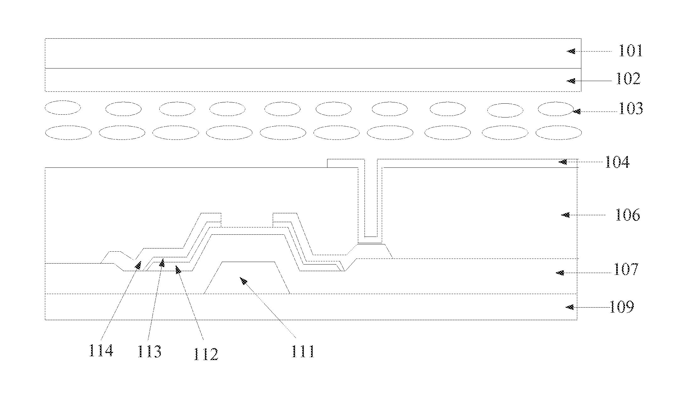
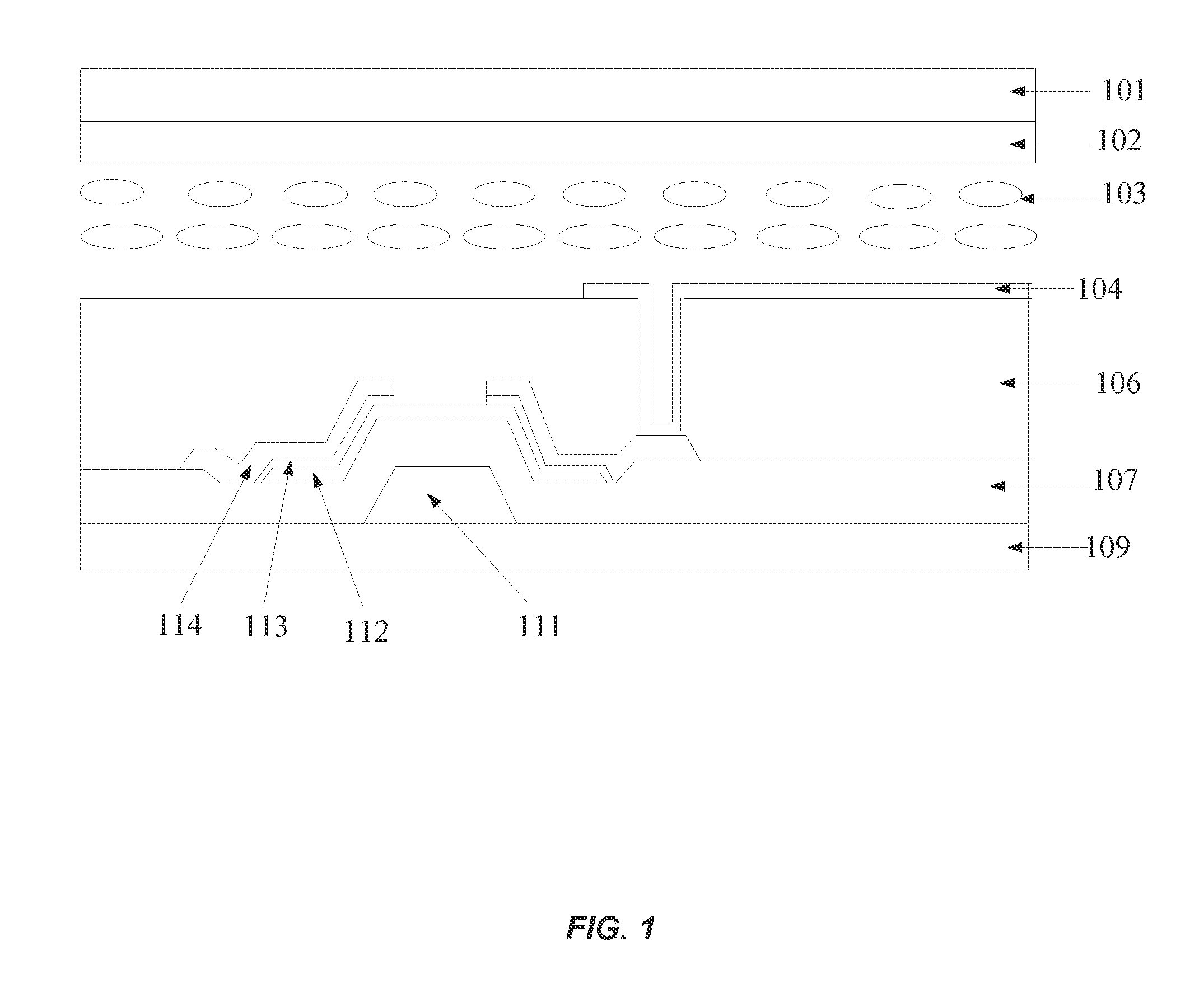
[0026]A TN (twisted nematic) LCD device is disclosed according to the first embodiment of the present invention. As shown in the sectional view in FIG. 1, the LCD device includes:

[0027]an array substrate 109, a color film substrate 101 disposed opposite to the array substrate 109, and a liquid crystal layer 103 disposed between the array substrate 109 and the color film substrate 101; wherein the array substrate and the color film substrate are generally glass substrates;

[0028]a gate electrode layer 121 disposed on a surface of the array substrate 109 facing the liquid crystal layer 103, where the gate electrode layer 121 includes gate electrodes 111 and scanning lines (not shown), the scanning lines and the gate electrodes 111 are formed on a same conductive layer and electrically connected to each other, the scanning line is used to switch on / off of a thin film transistor (TFT), and the gate electrode layer 121 may be made of a metal or a transparent conductive material such as in...

second embodiment

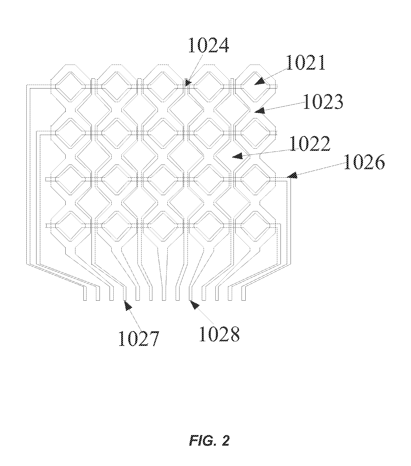
[0043]Different from the structure of the common electrode layer of the TN LCD device disclosed in the above embodiment, the plan view of the common electrode layer 102 of the TN LCD device according to the second embodiment of the present invention is shown in FIG. 3. A plurality of driving electrodes 21 are square electrodes arranged in an array, and strip-shaped sensing electrodes 22 are disposed between every two adjacent columns of driving electrodes. A dummy electrode 23 is disposed between a driving electrode 21 and a sensing electrode 22 adjacent to each other. Each of the dummy electrodes 23 is in a H shape and the H-shaped dummy electrodes in each row are connected to one another.

[0044]Similar to the first embodiment, driving electrodes 21 in a same row are connected to one another through a first wiring to form a driving line 26, strip-shaped sensing electrodes 22 in a same column are connected to one another through a second wiring to form a sensing line 27 and dummy ele...

third embodiment

[0050]Based on the TN LCD device disclosed in each of the above two embodiments, the TN LCD device integrated with the touch control function disclosed in this embodiment performs detection of touch signal by the principle of touch detection preferably in a capacitive touch panel. The capacitive touch panel may determine whether a touch occurs and detect the position of the occurring touch through detecting changes in the mutual capacitance between the sensing electrodes and the driving electrodes.

[0051]The principle of touch detection in the capacitive touch panel is shown in FIG. 4. A driving signal is applied to the driving electrode by the signal source41, and a detecting circuit 42 is used for signal detection. When a pointing object (generally a finger) touch the surface of the touch panel, there exists a current flowing into the finger, and ideally only the capacitance value of the mutual capacitor C1 between the sensing electrode and driving electrode is changed, and then th...


PUM


Abstract

A twisted nematic liquid crystal display device integrated with a touch control function is disclosed. The device includes an array substrate, a color film substrate disposed opposite the array substrate, and a liquid crystal layer disposed between the array substrate and the color film substrate. The device also includes a common electrode layer disposed on a surface of the color film substrate facing the liquid crystal layer. The common electrode layer includes a plurality of sensing electrodes, a plurality of driving electrodes, and a plurality of dummy electrodes located between the sensing electrodes and the driving electrodes. In addition, the sensing electrodes, the driving electrodes, and the dummy electrodes are insulated from one another.

Description

CROSS-REFERENCES TO RELATED APPLICATIONS[0001]This application claims the benefit of priority to Chinese Patent Application No. 201210567635.0, entitled “TN LIQUID CRYSTAL DISPLAY DEVICE AND TOUCH CONTROL METHOD THEREOF”, filed with the Chinese Patent Office on Dec. 24, 2012, the contents of which is incorporated herein by reference in its entirety.TECHNICAL FIELD[0002]The invention relates to liquid crystal display (LCD) technology, and in particular to a TN (twisted nematic) LCD device and a touch control method thereof.BACKGROUND OF THE INVENTION[0003]With the development of the liquid crystal display (LCD) technology, touch panels, as the most simple, convenient and natural way of human-machine interaction, are increasingly applied to the field of LCD. Depending on differences of the operational principle and media for transmitting information, the touch panels may be classified into four types: resistive touch panels, capacitive touch panels, infrared touch panels and surface a...

Claims


Application Information

Patent Timeline
IPC IPC(8): G02F1/1333G06F3/041
CPCG02F1/13338G02F1/134309G02F1/1396G06F3/0412G06F3/0446G02F1/134318G06F3/041
Inventor MA, JUNZHAO, LIJUN
Owner SHANGHAI TIANMA MICRO ELECTRONICS CO LTD
Learn More