Thermal radiation barrier for substrate processing chamber components

Active Publication Date: 2014-06-19
APPLIED MATERIALS INC
View PDF15 Cites 12 Cited by
  • Summary
  • Abstract
  • Description
  • Claims
  • Application Information

AI Technical Summary

Benefits of technology

The patent text discusses methods and devices for reducing thermal loss in a substrate support heater and associated chamber components. These methods include adding a coating, film, foil, or sheet to the heater body as a radiation barrier to minimize heat transfer outside of the heater. This helps improve thermal uniformity and efficiency of the heater. The radiation barrier can be made of yttrium-containing materials or other oxide minerals, and can be applied using different techniques such as sintering, plasma spray, or physical vapor deposition. The patent also describes a deposition chamber with a substrate support heater and a thermal barrier. The technical effect of these methods and devices is to improve the heating process in semiconductor manufacturing devices by reducing thermal loss and improving heating uniformity.

Problems solved by technology

However, a great portion of the energy applied to the heating element is lost through a backside of the disk-shaped body (opposite the substrate receiving surface) as well as minor surfaces (sides) of the disk-shaped body.
This lost energy is generally radiated from these surfaces to the chamber where the heater is installed.
The lost energy from these surfaces may detract from the efficiency of the process by freeing thermal energy that would otherwise be used to heat the substrate.
Thus, the conventional heaters provide inefficient use of power that is converted to thermal energy, and heating of peripheral chamber components requires supplemental cooling apparatus and methods to remove this excess heat, both of which contribute to cost of ownership.
Further, surfaces of chamber components that are heated by processes performed therein, such as chamber sidewalls, may lose this thermal energy to the surrounding environment.
This lost energy further reduces the efficiency of the manufacturing process and may add to cost of ownership.

Method used


Image

  • Thermal radiation barrier for substrate processing chamber components
  • Thermal radiation barrier for substrate processing chamber components
  • Thermal radiation barrier for substrate processing chamber components

Examples


Embodiment Construction

[0021]Methods and apparatus for a substrate support heater and associated chamber components having reduced energy losses are provided. Embodiments of the present invention provide systems, methods and apparatus using the substrate support heater for depositing films on a substrate and related cleaning processes in a corrosive plasma environment at temperatures greater than about 400 degrees C.

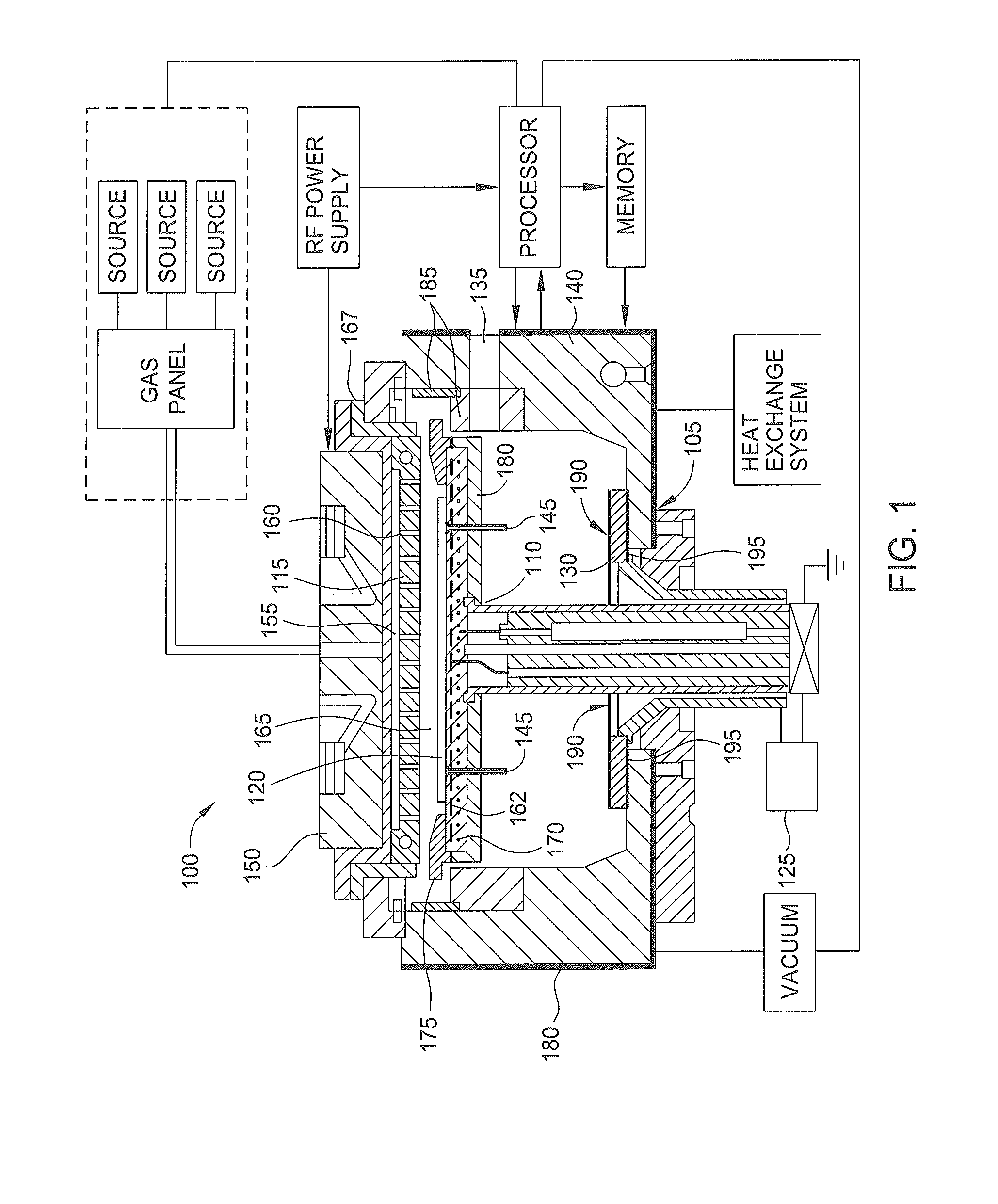
[0022]FIG. 1 is a schematic cross-sectional view of a deposition system 100. The deposition system 100 may be configured to deposit materials in the form of thin films on a substrate by dissociation of precursor fluids in a chemical vapor deposition (CVD) process, a plasma enhanced CVD (PECVD) process, or an atomic layer deposition (ALD) process. The deposition system 100 includes a reactor chamber 105, a substrate support heater 110 and a gas distribution showerhead 115 disposed in the interior volume of the reactor chamber 105. A radio frequency (RF) power supply provides radio-frequency pow...


PUM

PropertyMeasurementUnit
Thicknessaaaaaaaaaa
Volumeaaaaaaaaaa
Porosityaaaaaaaaaa

Abstract

An apparatus for a substrate support heater and associated chamber components having reduced energy losses are provided. In one embodiment, a substrate support heater is provided. The substrate support heater includes a heater body having a first surface to receive a substrate and a second surface opposing the first surface, a heating element disposed in the heater body between the first surface and the second surface, and a thermal barrier disposed on the second surface of the heater body, wherein the thermal barrier comprises a first layer and a second layer disposed on the first layer.

Description

CROSS-REFERENCE TO RELATED APPLICATIONS[0001]This application claims benefit of U.S. Provisional Patent Application Ser. No. 61 / 737,477, filed Dec. 14, 2012, which is hereby incorporated by reference herein.BACKGROUND OF THE INVENTION[0002]1. Field of the Invention[0003]Embodiments of the invention relate to a thermal barrier for use in chambers and chamber components utilized in thermal processes in the manufacture of electronic devices on substrates.[0004]2. Description of the Related Art[0005]Substrate processing chambers are commonly used in semiconductor manufacturing in order to fabricate electronic devices on a substrate. These chambers include a heater, which is typically in the form of a disk-shaped body, made of ceramic material, and includes a heating element embedded in the disk-shaped body. The heater is used to support the substrate and the heating element is used to heat the substrate to a desired temperature to facilitate an electronic device fabrication process on t...

Claims


Application Information

Patent Timeline
IPC IPC(8): H01L21/67H05B3/10
CPCH01L21/67103H01L21/68792
Inventor RAJ, GOVINDAMARTIN, DANIELHIRAHARA, ROBERT T.BHATNAGAR, ASHISHVASANTH, BOPANNARAO, PRASHANTHNARENDRNATH, KADTHALA R.
Owner APPLIED MATERIALS INC
Why Eureka
Try Eureka