Vibration tamper

a technology of vibration and tampering, applied in the field of vibration tamper, can solve the problems of affecting the operation of the building site, so as to achieve the effect of producing the driving energy necessary

Active Publication Date: 2014-06-12
BOMAG
View PDF8 Cites 5 Cited by
  • Summary
  • Abstract
  • Description
  • Claims
  • Application Information

AI Technical Summary

Benefits of technology

The present invention provides a vibration tamper with a superstructure that has a lower mechanical load than the substructure. This is achieved by placing at least one storage container on the superstructure. Additionally, the driving engine and the storage container are close to each other, which improves efficiency. The piping system can also be placed within the guide bar, resulting in efficient space usage and good protection against environmental factors.

Problems solved by technology

The numerous machines usually present on a building site together lead to considerable exhaust pollution for the persons active on the building site.
Problems are posed, in particular, by the regularly occurring high carbon monoxide concentrations and possibly by soot contamination.
This set of problems is particularly conspicuous when a vibration tamper is used in situations in which only a restricted working space is available, only small areas require compacting, and / or selective compacting measures are desired, as, for example, in trench and canal engineering.
Especially the accumulators necessary, therefore, are, however, still relatively expensive, and the operating periods thus attainable are comparatively short.

Method used


Image

  • Vibration tamper
  • Vibration tamper
  • Vibration tamper

Examples


Embodiment Construction

[0048]Like components are designated in the figures by like reference signs. Recurrent components are not necessarily individually denoted in each figure.

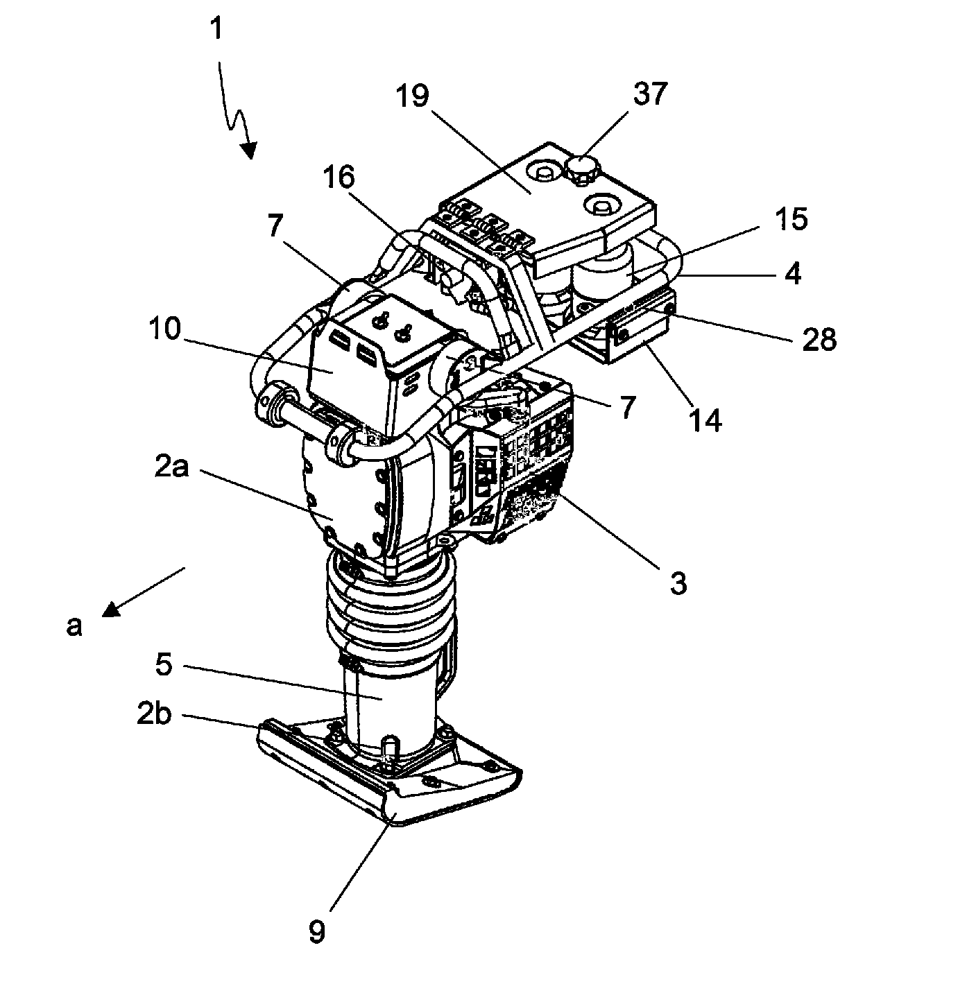
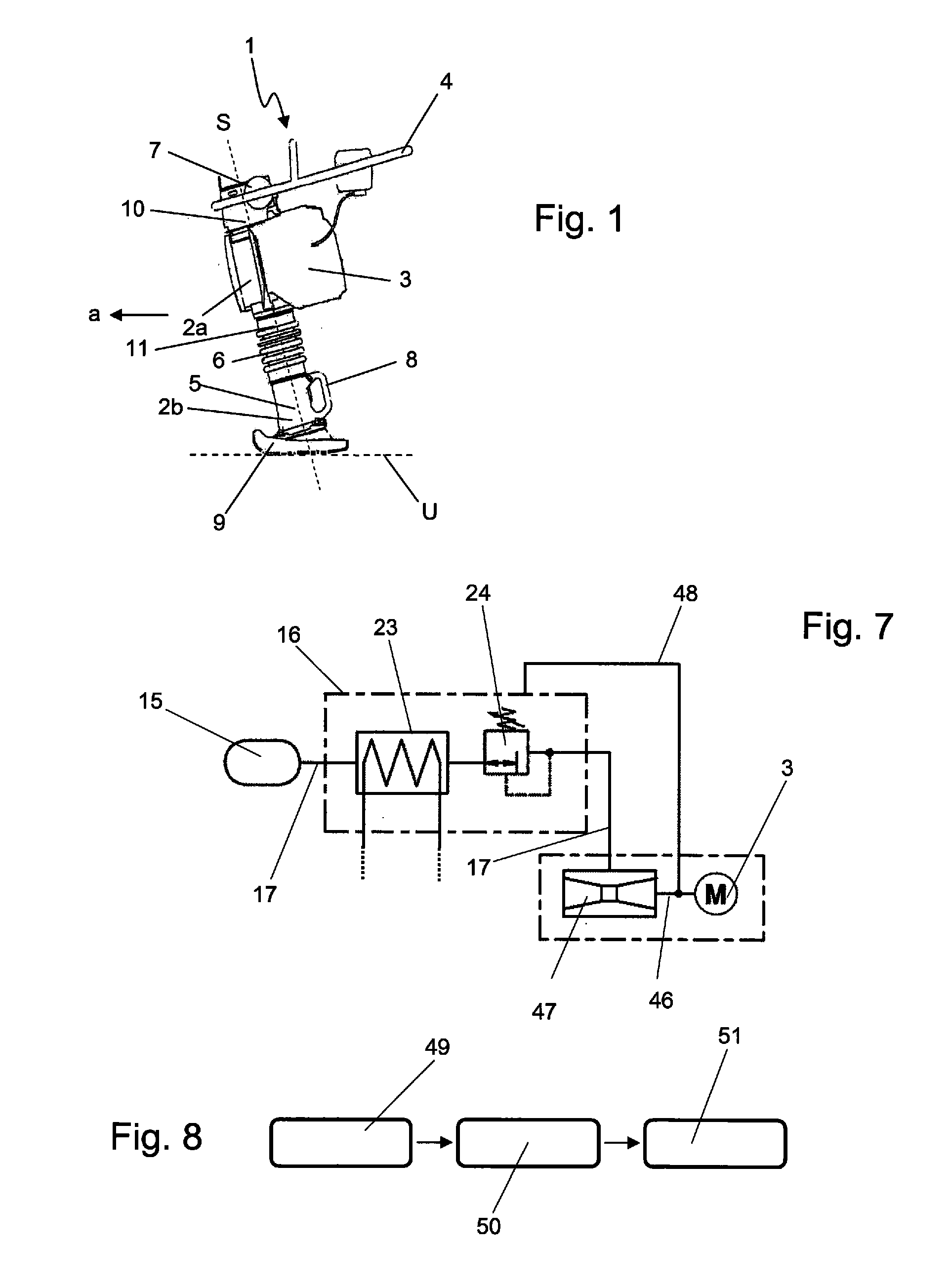
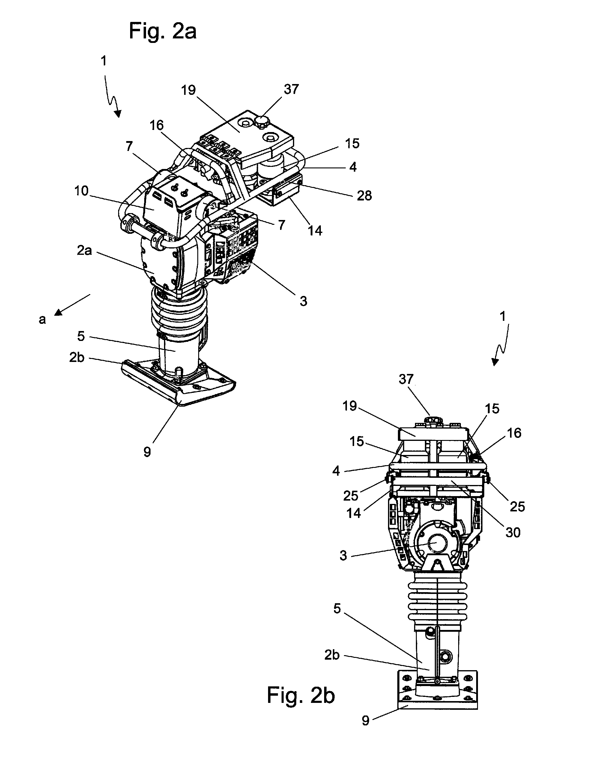
[0049]FIG. 1a shows a vibration tamper 1 comprising a superstructure 2a, wherein the superstructure 2a comprises a driving engine 3 and a guide bar 4. There are additionally present a substructure 2b comprising a compactor base 5 including a base plate 9 and a transport handle 8. The substructure 2b is linked to the superstructure 2a via a bellows 6. The guide bar 4 and the driving engine 3 on the superstructure 2a are indirectly interconnected via a machine frame 10 or interconnecting console 10. Inside the bellows 6 there is disposed a power transmission system, for example, a connecting rod, which converts the rotational driving power of the driving engine 3 to a linear motion and transfers it to the compactor base 5. Between the driving engine 3 and the compactor base 5, there is thus present, in all, a driving transmission 11,...


PUM


Abstract

The present invention relates to a vibration tamper, comprising a superstructure having a driving engine mounted on a machine frame and further having a guide bar, and further comprising a substructure having a compactor base driven by the driving engine and having a compactor plate and having a drive line, by means of which a drive connection between the driving engine and the compactor base is established such that the compactor base can move relatively to the superstructure along a compactor axis while executing at least one compacting amplitude. The driving engine of the vibration tamper is a liquid gas powered driving engine, wherein the superstructure and, more particularly, the guide bar on the superstructure, comprises a storage container for liquid gas, and wherein a gas supply line is provided to supply evaporated liquid gas to the driving engine.

Description

CROSS-REFERENCE TO RELATED APPLICATIONS[0001]The present application claims priority under 35 U.S.C. §119 of German Patent Application No. 10 2012 024 222.0, filed Dec. 11, 2012, the disclosure of which is hereby incorporated herein by reference in its entirety.FIELD OF THE INVENTION[0002]The present invention relates to a vibration tamper for ground compaction.BACKGROUND OF THE INVENTION[0003]A generic vibration tamper includes a superstructure comprising a driving engine mounted on a machine frame and further comprising a guide bar, and further includes a substructure comprising a compactor base driven by the driving engine and comprising a compactor plate and a drive line, by means of which a drive connection between the driving engine and the compactor base is established such that the compactor base is capable of moving relatively to the superstructure along a compactor axis while executing at least one compacting amplitude. A generic vibration tamper is, for example, disclosed...

Claims


Application Information

Patent Timeline
Patent Type & Authority Applications(United States)
IPC IPC(8): E02D3/046
CPCE02D3/046E01C19/38
Inventor BECKER, JOSTKRINGS, ALBERTUS
Owner BOMAG
Why Eureka
Try Eureka