
Display device

a display device and display technology, applied in the field of display devices, can solve the problems of color shift, limited user information range, and limited user information range, and achieve the effect of inexpensive and robust display

Active Publication Date: 2014-06-05
SCHOTT AG
View PDF8 Cites 27 Cited by
  • Summary
  • Abstract
  • Description
  • Claims
  • Application Information

AI Technical Summary

Benefits of technology

The invention aims to create a cheap and durable display device made of transparent, colored glass ceramics that can produce any desired and pre-defined color effects for the user.

Problems solved by technology

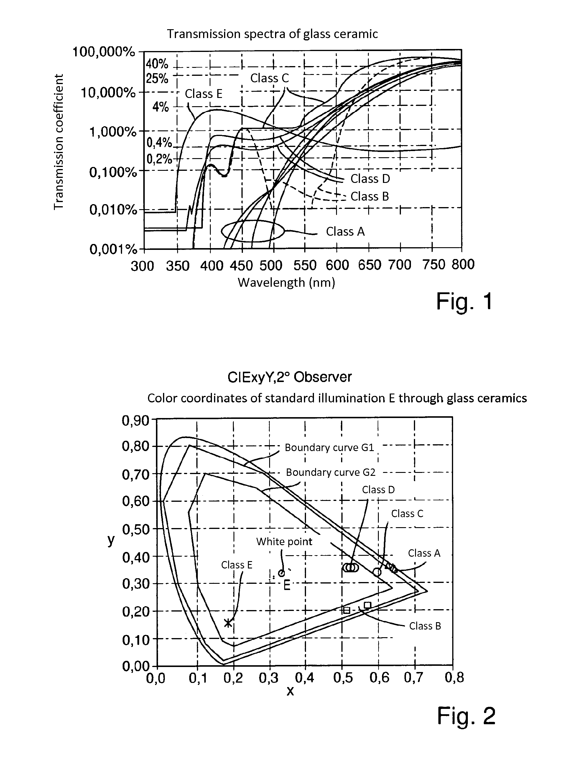
Based on the coloring of the glass-ceramic cooktop and the very limited selection of colored LED displays, the range of colors that are available for user information is very greatly limited.
By broadening the transmission spectrum also to the blue wavelength region, the color possibilities for displays have in fact been expanded, but based on the small number of different-color LED displays, the number of colors visible to the user is also limited in the case of these glass-ceramic cooktops.
Color shifts may occur over long periods of use due to the different aging of the LEDs of different colors.

Method used


Image

  • Display device
  • Display device
  • Display device

Examples


embodiment example 1

Dark Glass Ceramics with Smooth Bottom

Production Binder A

[0059]0.08 mole of GPTES (glycidyloxypropyltriethoxysilane) containing 0.02 mole of TEOS (tetraethoxysilane) is hydrolyzed with water mixed with 0.125 mole of para-toluic acid. Then the solvent is removed in a rotary evaporator and 22.6 g of binder are obtained.

Production Binder B

[0060]0.04 mole of MPTMS (methacryloxypropyltrimethoxysilane) containing 0.02 mole of TEOS (tetraethoxysilane) and 0.04 mole of MTEOS (methyltriethoxysilane) is hydrolyzed with water mixed with 0.125 mole of para-toluic acid. Then the solvent is removed in a rotary evaporator.

[0061]A commercially available dispersion of 15-nm SiO2 particles in diethylene glycol monopropyl ether is used as a nanoparticle-containing solution.

[0062]The initiator solution contains 50 mass % of heat-activatable initiator methylimidazole in ethylene glycol monopropyl ether.

[0063]A color which was composed of the following components was printed by screen printing onto the b...

embodiment example 2

Dark Glass Ceramics with Dimpled or Knobby Bottom

[0069]A leveling layer of polyurethane resin was printed by screen printing on a dimpled dark glass-ceramic product of the type CERAN HIGHTRANS Eco® and then thermally cured. The fluctuation in layer thickness was [0070]32% binder A[0071]60% nanoparticle-containing sol-gel solution[0072]2% initiator solution[0073]6% Blue 807 dye 94030

[0074]Drying was conducted for 3 min under UV radiation.

[0075]The fluctuation in layer thickness was <3 um; the light of a white LED was shown to be homogeneously white.

embodiment example 3

Dark Glass Ceramics with Dimpled or Knobby Bottom

[0076]A leveling layer of polyurethane resin was printed by screen printing on a dimpled dark glass-ceramic product of the type CERAN HIGHTRANS Eco® and then thermally cured. The fluctuation in layer thickness was [0077]32% binder B[0078]60% nanoparticle-containing sol-gel solution[0079]2% initiator solution[0080]6% Blue 807 dye 94030

[0081]Drying was conducted for 60 min under IR radiation combined with convection.

[0082]The fluctuation in layer thickness was <3 um; the light of a white LED was shown to be homogeneously white.


PUM

PropertyMeasurementUnit
vapor pressureaaaaaaaaaa
thicknessaaaaaaaaaa
thicknessaaaaaaaaaa

Abstract

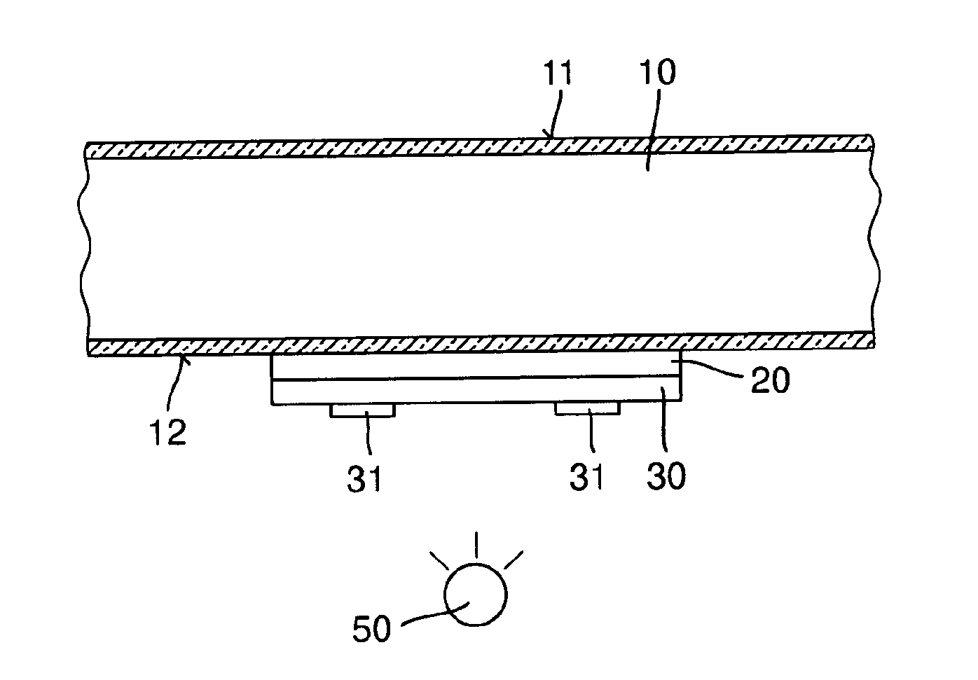
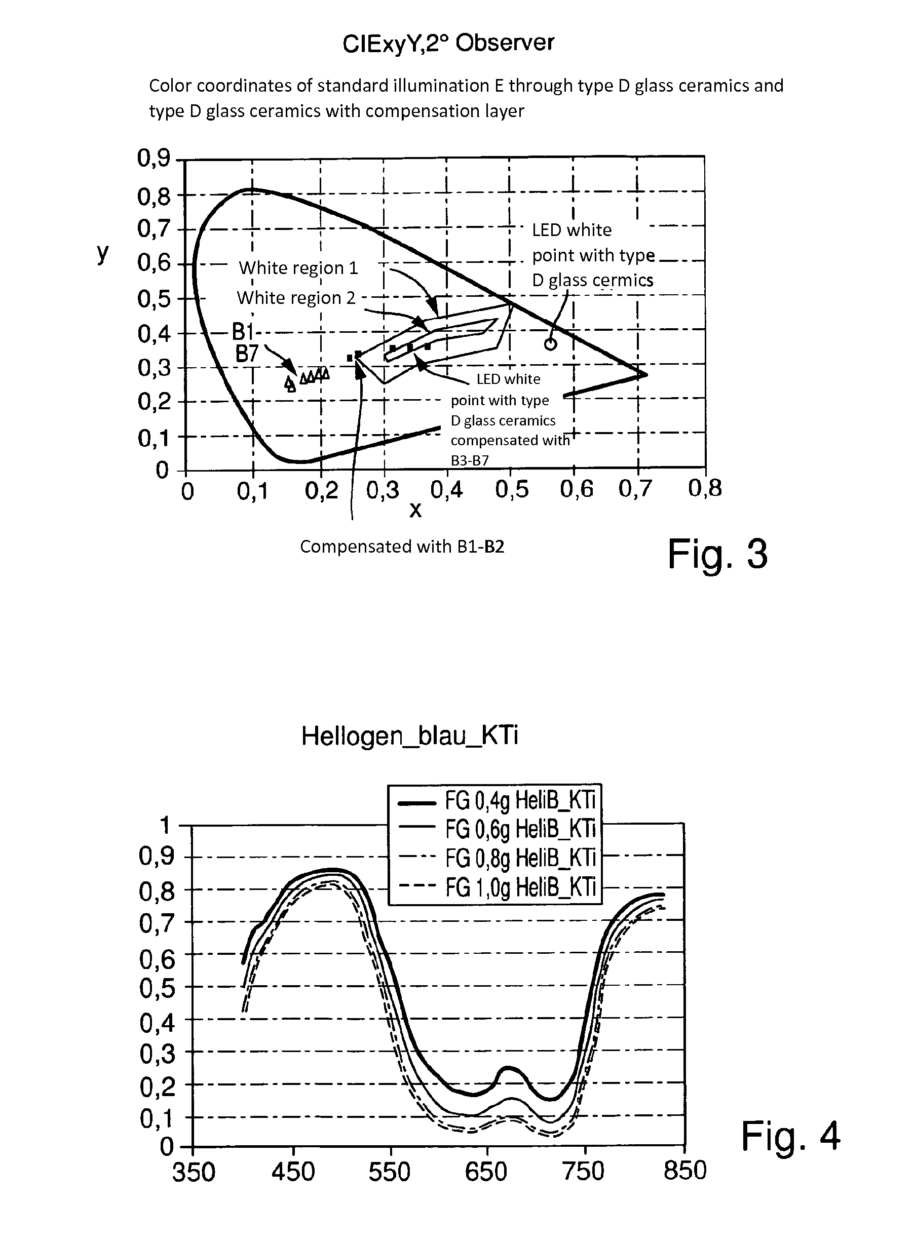
A display device is provided that is a transparent, colored glass-ceramic with a display face on the front, an illumination face on the back, and at least one light-emitting element being disposed in the region of the illumination face. The display device further includes a color compensation filter in the form of a color layer introduced directly or indirectly on the glass ceramics.

Description

CROSS REFERENCE TO RELATED APPLICATIONS[0001]This application is a U.S. National Stage Entry under 35 U.S.C. §371 of PCT / EP2012 / 058199, filed on May 4, 2012, which claims benefit under 35 U.S.C. §119(a) of German Patent Application No. 10 2011 050 870.8, filed Jun. 6, 2011, the entire contents of both of which are incorporated herein by referenceBACKGROUND OF THE INVENTION[0002]In order to improve user experience, modern glass-ceramic cooktops are equipped with signal lamps or 7-segment displays. Here, the cooking surface itself is composed of a transparent, colored glass-ceramic panel (substrate), which usually appears black in top view. The signal lamps provide the user with information concerning the ON status of the cooktop or individual cooking zones, the control setting and also whether the cooking zone is still hot after it is turned OFF. LED lamps are usually employed as lighting means.[0003]Based on the coloring of the glass-ceramic cooktop and the very limited selection of...

Claims


Application Information

Patent Timeline
Patent Type & Authority Applications(United States)
IPC IPC(8): F21K99/00F21V9/40
CPCF24C15/102G02B5/223G02B5/226F24C7/083B25H3/003C03C17/002C03C2217/72G02B5/02F24C7/082G09F9/33H05B3/746H05B6/1218F21V33/0044F21K9/64
Inventor KNOCHE, SILKEBOCKMEYER, MATTHIASANTON, ANDREAZENKER, THOMASOHL, GEROLD
Owner SCHOTT AG
Learn More