
Leakage Seeker

Inactive Publication Date: 2011-05-05
INFICON GMBH
View PDF14 Cites 5 Cited by
  • Summary
  • Abstract
  • Description
  • Claims
  • Application Information

AI Technical Summary

Benefits of technology

[0011]The volume of the buffer volume is preferably at least three times as large as the pumping volume of the feed pump. This provision is based on a feed pump of the type for discontinuous conveyance which, when operated, will generate corresponding pressure surges. According to a particularly preferred embodiment, the feed pump is formed as a displacement pump for exclusively discontinuous conveyance. Displacement pumps, e.g. membrane pumps, are simple in construction as well as robust and inexpensive, and thus find preferred application as feed pumps in leak detectors.
[0014]According to a preferred embodiment, there is provided at least one further arrangement of buffer volume and restrictor. This buffer-volume / restrictor arrangement can be located immediately adjacent to the first buffer-volume / restrictor arrangement but can also be located separately from the first arrangement. By the provision of a second buffer-volume / restrictor arrangement, the filter parameters of the overall arrangement comprising said two buffer-volume / restrictor arrangements can be still better adapted to the requirements. If the flow sensor is arranged between the sniffing opening and the feed pump, the second buffer-volume / restrictor arrangement can be located between the sniffing opening and the flow sensor while the first buffer-volume / restrictor arrangement is arranged between the feed pump and the flow sensor. Thereby, given this placement of the flow sensor, the latter will be protected from pressure surges towards both sides.
[0015]Preferably, the flow sensor is a micromechanical flow sensor. Further, the flow sensor can be a thermal flow sensor. Micromechanical flow sensors are relatively inexpensive and precise, particularly if designed as thermal flow sensors. However, micromechanical flow sensors are very vulnerable towards pressure surges. The use of the buffer-volume / restrictor arrangement makes it possible to utilize micromechanical thermal flow sensors without deterioration of the reliability of the leak detector caused by the micromechanical thermal flow sensor.

Problems solved by technology

If a gas leak exists, the test gas will evade from the test item to the outside.
Practice has shown that the flow sensor is a relatively vulnerable component which is susceptible to frequent damage.
Pressure surges of the feed pump are caused upon switch-on and switch-off of the feed pump but are caused particularly by the feed pump during the conveying process, especially in case of displacement pumps designed for discontinuous conveyance of gas.
However, micromechanical flow sensors are very vulnerable towards pressure surges.

Method used


Image

  • Leakage Seeker
  • Leakage Seeker

Examples


Embodiment Construction

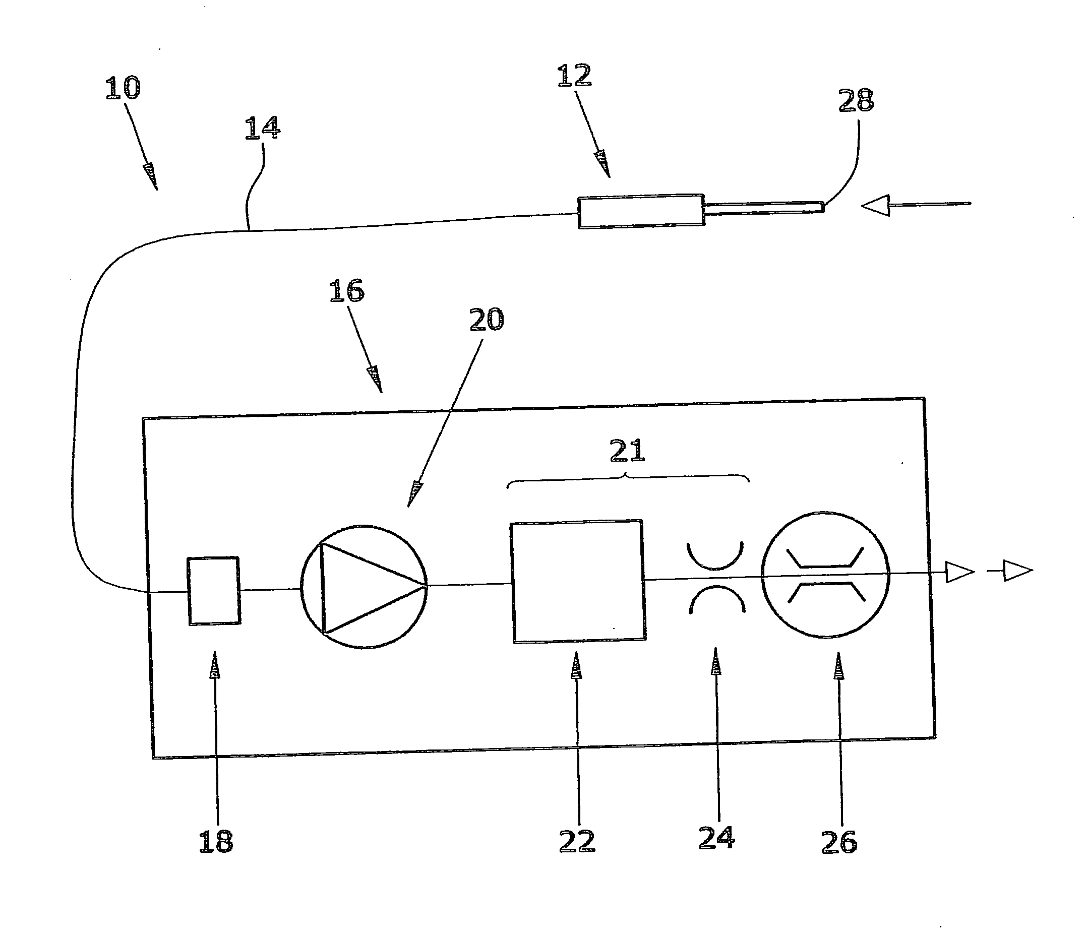
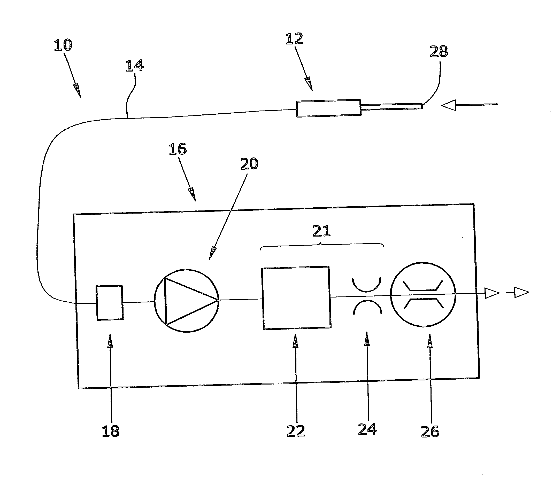
[0018]Shown in the FIGURE is a leak detector 10 substantially consisting of a handpiece 12, a sniffing line 14 and a detection unit 16. Detection unit 16 comprises—in serial arrangement—a gas detector 18, a feed pump 20, a buffer volume 22, a restrictor 24 as well as a flow sensor 26.

[0019]Said handpiece 12 is also referred to as a sniffing probe and on its distal end is provided with a sniffing opening 28 for suctional intake of gas. Via the sniffing line 14 which is formed as a flexible tube, the sucked gas will flow to the gas detector 18 which is operative to detect a test gas such as e.g. helium in the sucked gas, in case that test gas is present. Gas detector 18 can be configured as a mass spectrometer, for instance.

[0020]Feed pump 20 is a pre-vacuum feed pump formed as a displacement pump, e.g. as a membrane pump. Displacement pumps inherently generate pressure surges during the opening and closing of the pumping chamber. Feed pump 20 generates a volume flow of about 150 cm3 / ...


PUM


Abstract

A leak detector having a pre-vacuum feed pump, a gas detector and a flow sensor. The detector also includes a buffer volume and a restrictor to be arranged between the feed pump and the flow sensor. This protects the flow sensor against pressure surges generated by the feed pump.

Description

BACKGROUND[0001]1. Field of the Invention[0002]The disclosure relates to a leak detector comprising a pre-vacuum feed pump, a gas detector and a flow sensor.[0003]2. Discussion of the Background Art Leak detectors, also referred to as leak sniffing devices, are used for scanning a test item containing a test gas. If a gas leak exists, the test gas will evade from the test item to the outside. The test gas will be detected by the gas detector or gas sensor and be reported. The pre-vacuum feed pump has the function of continuously conveying gas from the vicinity of the test item and to supply said gas to the gas detector.[0004]In the gas path, a flow sensor for detecting the gas flow is arranged upstream or downstream of the feed pump. On the one hand, the flow sensor is operative to perform a controlling and monitoring function, i.e. for controlling whether the conveying path is possibly clogged and, respectively, whether the feed pump is working without disturbances. On the other ha...

Claims


Application Information

Patent Timeline
IPC IPC(8): G01M3/20
CPCG01M3/205G01M3/202
Inventor GERDAU, LUDOLFROLFF, RANDOLF PAULROLFF, NORBERTWETZIG, DANIEL
Owner INFICON GMBH
Learn More