
Flat display panel having narrow bezel

a flat display panel and bezel technology, applied in the field of flat display panels, can solve the problems of demerits of horizontal electric field type lcd and damage to oxide semiconductor materials, and achieve the effect of minimizing the bezel area

Active Publication Date: 2014-06-05
LG DISPLAY CO LTD
View PDF15 Cites 17 Cited by
  • Summary
  • Abstract
  • Description
  • Claims
  • Application Information

AI Technical Summary

Benefits of technology

This patent text suggests a display panel for flat panel displays that has a narrow bezel structure. This is achieved by minimizing the area for disposing the common line, which is formed at the side portions of the display panel. Additionally, the text suggests that a flat display panel can be created by forming the gate driving circuit directly on the substrate of the display panel. By using a conductive sealing material to connect multiple common lines, the bezel area can be minimized. Overall, this invention reduces the size of the display panel, making it more portable and aesthetically appealing.

Problems solved by technology

However, the horizontal electric field type LCD may have demerits such as low aperture ratio and transitivity ratio of the back light.
In detail, when dividing the source electrode S and the drain electrode D by an etching method, the oxide semiconductor material may be damaged by an etchant intruded into the oxide semiconductor material from this etched portion.

Method used


Image

  • Flat display panel having narrow bezel
  • Flat display panel having narrow bezel
  • Flat display panel having narrow bezel

Examples


Embodiment Construction

[0044]Referring to attached figures, preferred embodiments of the present disclosure will be described. Like reference numerals designate like elements throughout the detailed description. However, the present disclosure is not restricted by these embodiments but can be applied to various changes or modifications without changing the technical spirit. In the following embodiments, the names of the elements are selected for ease of explanation and may be different from actual names.

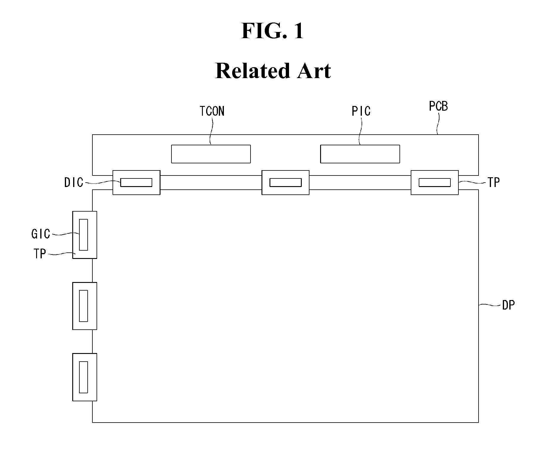
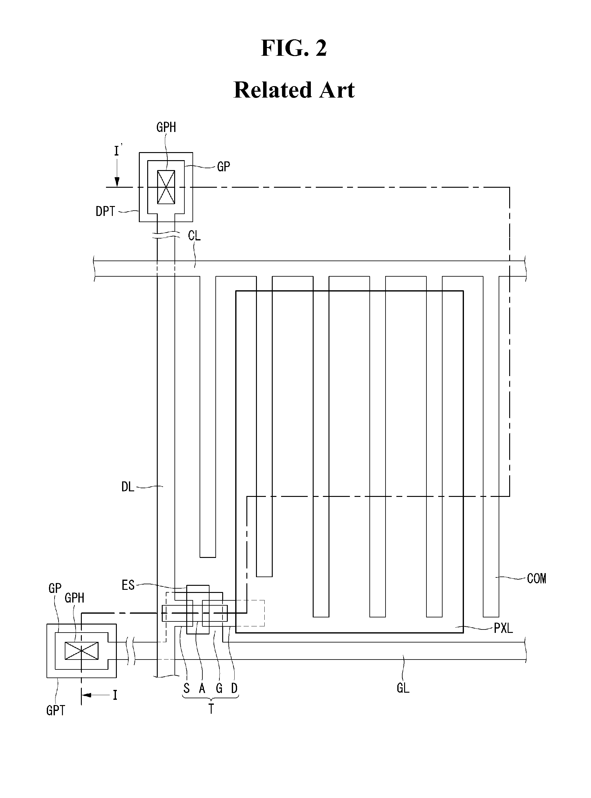
[0045]Referring to FIGS. 4 to 6, we will explain about embodiments of the present disclosure. FIG. 4 is a plane view illustrating the structure of a flat panel display formed by GIP method according to the present disclosure. Referring to FIG. 4, at the one side of the upper portion of the display panel DPL, a data driver DIC may be disposed and connected to the data lines using the TAB method. Otherwise, a gate driver GP is directly formed at the non-display area NA which is one outer side of the pixel ar...


PUM

PropertyMeasurementUnit
widthaaaaaaaaaa
widthaaaaaaaaaa
widthaaaaaaaaaa

Abstract

The present disclosure relates to reducing bezel area of a flat display panel comprising a substrate with a non-display area surrounding a display area, the display area comprising common lines coupled to corresponding rows of pixels; and a gate driver formed in the non-display area. The display may further include a conductive sealing region formed in the non-display area and configured to supply a common line voltage; and a plurality of common pads formed within the conductive sealing region and each coupled to a corresponding one of the common lines to apply a common line voltage to the rows of pixels. Alternatively, the display may further include a vertical common line formed in the non-display area between the gate driver and the display area, the vertical common line extending from top to bottom of the non-display area and coupled to said common lines to apply a common voltage.

Description

CROSS-REFERENCE TO RELATED APPLICATION[0001]This application claims priority to Republic of Korea Patent Application No. 10-2012-0138011 filed on Nov. 30, 2012, which is incorporated by reference herein in its entirety.BACKGROUND OF THE INVENTION[0002]1. Field of the Invention[0003]The present disclosure relates to a flat panel display in which the display area is maximized by reducing the width of the bezel area. Especially, the present disclosure relates to a large area flat panel display in which the display area is maximized by replacing a conductive sealing material with the common line for reducing the width of the bezel area.[0004]2. Discussion of the Related Art[0005]Various flat panel displays (or ‘FPD’) are developed for overcoming the many drawbacks of the cathode ray tube (or ‘CRT’) such as heavy weight and bulk volume. The flat panel display devices include the liquid crystal display device (or ‘LCD’), the field emission display (or ‘FED’), the plasma display panel (or ...

Claims


Application Information

Patent Timeline
Patent Type & Authority Applications(United States)
IPC IPC(8): G02F1/1362G02F1/1368
CPCG02F1/1339G02F1/13454G02F2201/121G02F2202/16G02F1/134372G02F1/1345G09F9/00
Inventor HEO, SEUNGHOSO, BYEONGSEONG
Owner LG DISPLAY CO LTD
Learn More