
Method and Apparatus for Detecting Airtight State of Machine-Tool Window

Active Publication Date: 2014-06-05
DMG MORI SEIKI CO LTD
View PDF30 Cites 8 Cited by
  • Summary
  • Abstract
  • Description
  • Claims
  • Application Information

AI Technical Summary

Benefits of technology

This patent describes a method and apparatus for accurately detecting the airtight state of two transparent or translucent window plates that are joined together with a pre-determined distance between them. By changing the allowable range for judging based on the pressure variation over time, it is possible to accurately determine if the window is airtight or not, and take appropriate measures to prevent accidents caused by a tool or a workpiece penetrating the window and shooting out. Additionally, the patent also suggests using different materials with high wear resistance and impact resistance but low resistance to coolant for the window plates to provide better protection against airtightness issues.

Problems solved by technology

However, even the window having the structure in which the glass plate and the polycarbonate plate are airtightly joined together with a pre-determined distance between them has a problem as described below.
That is, although, if the airtightness of the joined portion between the glass plate and the polycarbonate plate of the window is secured, coolant is not allowed to enter between the glass plate and the polycarbonate plate and therefore the reduction of toughness and impact resistance of the polycarbonate plate due to coolant does not occur, the airtightness has not been fully ensured conventionally.
Further, even if the airtightness is ensured at the time of manufacturing, it is possible that a seal member does not have sufficient resistance to coolant, and in this case there is the fear that the airtightness is lowered by deterioration over time of the seal member.

Method used


Image

  • Method and Apparatus for Detecting Airtight State of Machine-Tool Window
  • Method and Apparatus for Detecting Airtight State of Machine-Tool Window
  • Method and Apparatus for Detecting Airtight State of Machine-Tool Window

Examples


Embodiment Construction

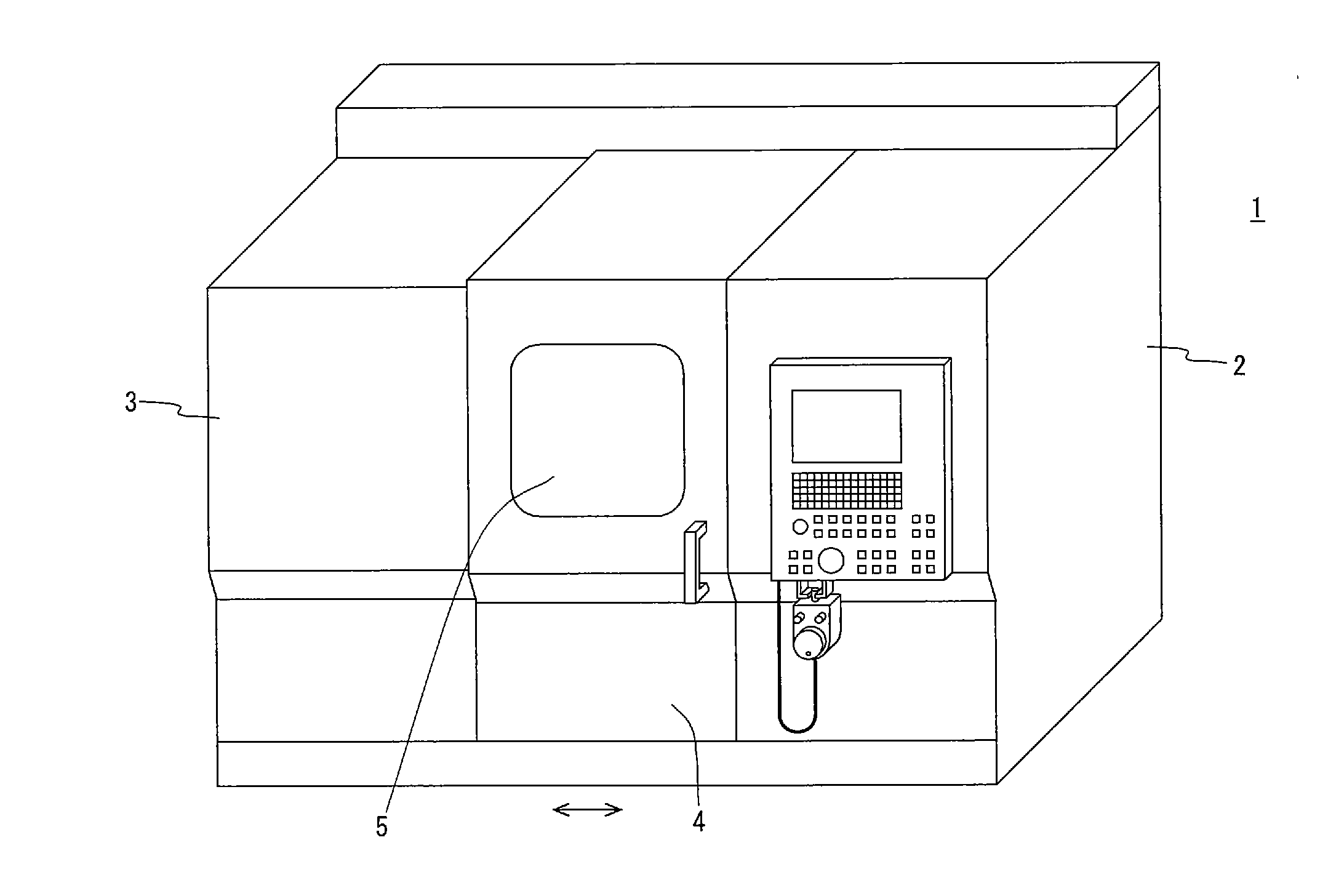
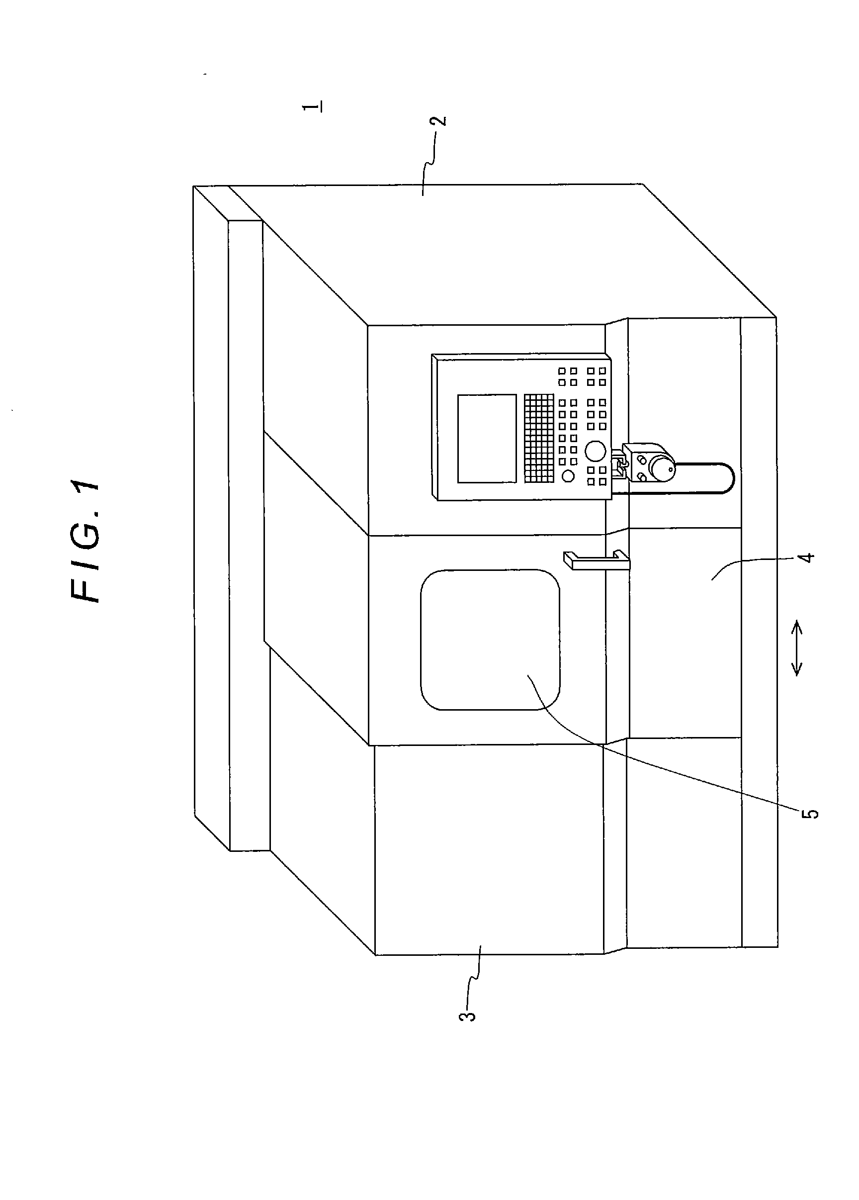
[0048]Hereinafter, a specific embodiment of the present disclosure will be described with reference to the drawings. FIG. 1 is a perspective view of the whole of a machine tool according to the embodiment, FIG. 2 is an illustration showing a schematic configuration of an airtight state detecting apparatus according to the embodiment, and FIG. 3 is a partial cross-sectional view taken along the arrow A-A of FIG. 2.

Machine Tool and Window

[0049]First of all, a machine tool 1 and a window 5 of the embodiment are described. As shown in FIG. 1, the machine tool 1 of the embodiment is specifically an NC lathe, and its structures such as a bed, a headstock, a tool rest, etc. are covered by two fixed covers (cover bodies) 2, 3 and a door cover (cover body) 4 which is slidable in the directions indicated by the arrow, and the machine tool 1 has a structure in which a machining region is separated from the outside by the fixed covers 2, 3 and the door cover 4.

[0050]The fixed covers 2, 3 are ea...


PUM


Abstract

Methods and apparatus for detecting machine tool window airtightness includes an airtight state detector, having a sensor detecting the pressure in a space of the window, and a judging section for determining appropriateness of the airtight state of the space based on a pressure value from the pressure sensor and outputting a judgment result. Pressure in the window space, which initially may be pressurized or pressure-reduced, is detected intermittently by the pressure sensor, and the judging section determines appropriateness of the airtight state of the window on the basis of a variation state of the detected pressure.

Description

TECHNICAL FIELD [0001]The present disclosure relates to a method and an apparatus for detecting, on a machine tool provided with a cover body having a window, an airtight state of the window, the window comprising two transparent or translucent window plates which are airtightly joined together with a pre-determined distance between them.BACKGROUND [0002]Usually, taking into consideration safety and environmental aspects, a machine tool is provided with a cover body for dividing a machining region from an external region and the cover body is provided with a window so that the machining region can be observed from the outside thereof.[0003]As an example of such a cover body having a window, conventionally, the cover body disclosed in the Japanese Unexamined Patent Application Publication No. 3-166037 has been known. The cover body (specifically, a slide door) disclosed in this published application is made of a plate-shaped polycarbonate and has a structure in which a glass plate is...

Claims


Application Information

Patent Timeline
IPC IPC(8): G01M3/04
CPCG01M3/04B23Q11/08G01M3/3272
Inventor ONO, KATSUHIKOSATO, NORIONISHIMURA, KIMIYUKI
Owner DMG MORI SEIKI CO LTD
Learn More