Sacrificial Cover Layers for Laser Drilling Substrates and Methods Thereof
a technology of laser drilling substrates and sacrificial cover layers, which is applied in the manufacture of glass making apparatuses, manufacturing tools, transportation and packaging, etc., can solve the problems of inability to produce small-diameter holes with acceptablely low defects, easy cracking of entrance holes, and micro-cracks or “checks" to achieve the effect of reducing the irregularity of precision holes
- Summary
- Abstract
- Description
- Claims
- Application Information
AI Technical Summary
Benefits of technology
Problems solved by technology
Method used
Image
Examples
example 1
[0151]Example 1 shows the effect of forming holes in a glass article according to a sacrificial glass cover layer method described herein.
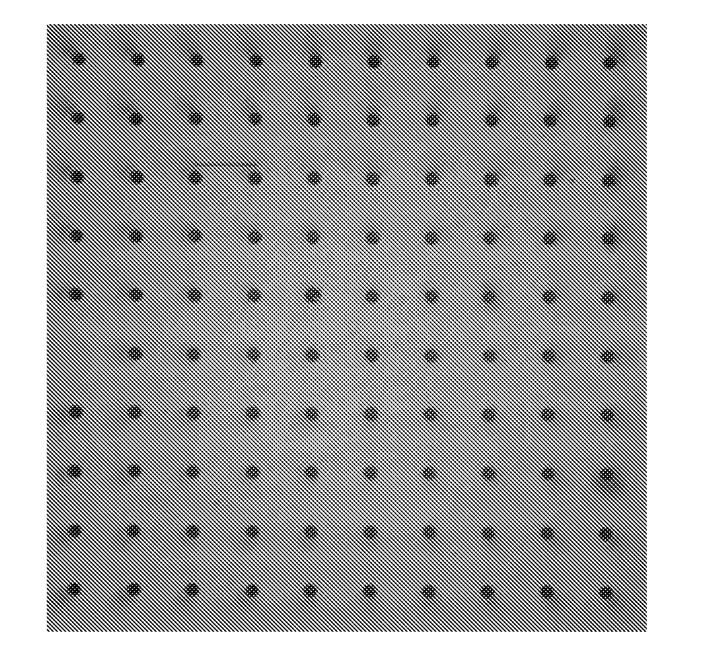
[0152]A 355 nm nanosecond pulsed laser is first used to form through holes in a sacrificial glass cover layer made of Eagle XG, manufactured by Corning, Inc and having a thickness of 320 μm. Subsequently, holes are formed in the glass article made of Eagle XG, manufactured by Corning, Inc. by pulsing the laser through the through holes formed in the sacrificial glass cover layer and onto a surface of the glass article. The spacing of the holes is about 250 μm and the post-etch diameter of the holes is about 35 μm. FIG. 16 shows top views of the glass article. The photograph on the left shows the glass article before etching and the photograph on the right shows the glass article after etching. The inlay in FIG. 16 shows the holes at higher magnification. As can be seen from FIG. 16, the holes formed in the glass article have very circular shapes, ...
example 2
[0153]Example 2 shows the effect of forming blind holes (i.e., holes that do not penetrate the glass article) in a glass article according to a sacrificial glass cover layer method described herein.
[0154]A 355 nm nanosecond pulsed laser is first used to form through holes in a sacrificial glass cover layer made of Eagle XG, manufactured by Corning, Inc and having a thickness of 150 μm. Subsequently, holes are formed in the glass article made of Eagle XG, manufactured by Corning, Inc. by pulsing the laser through the through holes formed in the sacrificial glass cover layer and onto a surface of the glass article. The diameter of the holes is about 36 μm and the holes are about 280 μm deep. FIG. 17 shows a top view of the glass article after etching. FIG. 18 shows a side view of the holes after etching. The inlay in FIG. 18 shows the holes at higher magnification. As can be seen from FIGS. 17 and 18, the blind holes formed in the glass article have very circular shapes, even after th...
example 3
[0155]Example 3 compares the effect of focus position on hole symmetry and quality using a direct laser drilling method and a sacrificial glass cover layer method as described herein.
[0156]A 355 nm nanosecond pulsed laser is used to form holes in a glass article made of Eagle XG, manufactured by Corning, Inc. A direct laser drilling method as described in Comparative Example 1 and a laser drilling method using a sacrificial glass cover layer as described in Example 1 is used. The focus position of the laser was adjusted from −100 μm, 0 μm, 100 μm, 200 μm, and 250 μm where negative numbers indicate a focus location above the topmost glass surface and positive numbers indicate a focus location below the topmost glass surface. FIG. 19 shows the entrance holes of the glass articles before etching. The top row of photographs shows the glass articles prepared by direct laser drilling and the bottom row of photographs show the glass articles prepared using a sacrificial glass cover layer. ...
PUM
| Property | Measurement | Unit |
|---|---|---|
| wavelength | aaaaa | aaaaa |
| thickness | aaaaa | aaaaa |
| thickness | aaaaa | aaaaa |
Abstract
Description
Claims
Application Information
 - R&D
- Intellectual Property
- Life Sciences
- Materials
- Tech Scout
- Unparalleled Data Quality
- Higher Quality Content
- 60% Fewer Hallucinations
Browse by: Latest US Patents, China's latest patents, Technical Efficacy Thesaurus, Application Domain, Technology Topic, Popular Technical Reports.
© 2025 PatSnap. All rights reserved.Legal|Privacy policy|Modern Slavery Act Transparency Statement|Sitemap|About US| Contact US: help@patsnap.com


