
Method and System for Recovery of 3D Scene Structure and Camera Motion From a Video Sequence

a technology of scene structure and camera motion, applied in image data processing, instruments, character and pattern recognition, etc., can solve the problems of reducing the processing load, affecting situational awareness, and affecting the accuracy of 3d data extraction from 2d image data, so as to facilitate the use of a single computational framework and reduce the processing load

Inactive Publication Date: 2014-05-29
TRINITY COLLEGE DUBLIN
View PDF4 Cites 64 Cited by
  • Summary
  • Abstract
  • Description
  • Claims
  • Application Information

AI Technical Summary

Benefits of technology

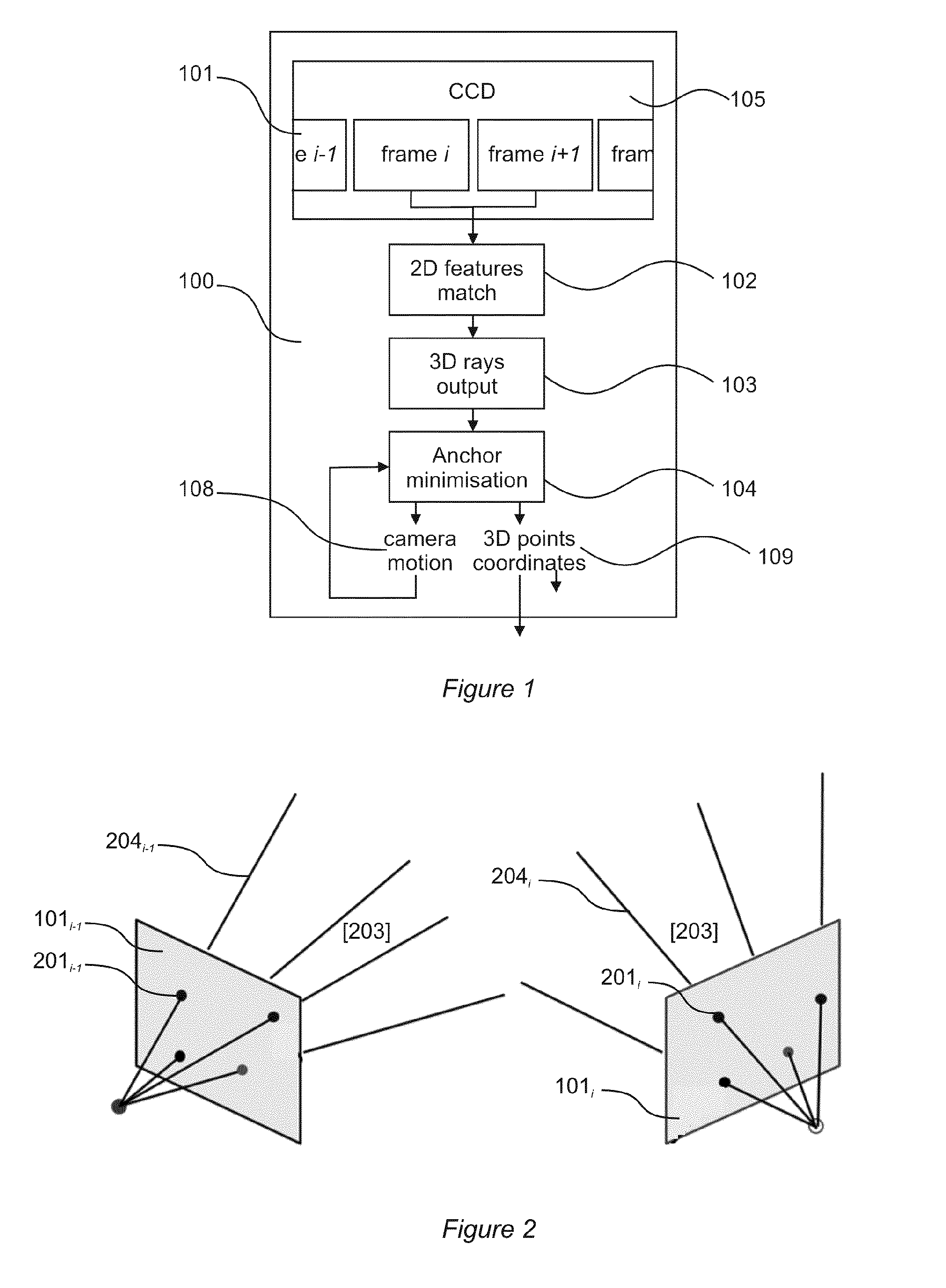
The present invention provides an improved method and system for extracting 3D data from 2D source data in real-time. The method and system use a ray based approach instead of a point based approach for calculating the camera position in a 3D scene, resulting in higher accuracy and processing speed. The system also includes a data processing means that matches 2D features from previous image frames and generates a 3D ray by back-projection from each 2D feature, which is then subjected to an anchor-based minimization process to determine camera motion parameters and 3D scene points coordinates, thereby recovering a structure of the 3D scene.

Problems solved by technology

A more widespread use of these methods in image processing applications referred to as ‘augmented reality’ applications, the purpose of which is to embed, impart or map additional information to 2D image data captured in real-time by imaging means, remains impeded by the amount of data processing resources required for accurately extracting 3D data from 2D image data.
The constant growth of air travel over the past decades has resulted both in larger aircrafts being constantly developed for carrying ever more passengers and cargo, recently resulting in such large airliners as the Airbus A380, Boeing 747-8 and Antonov An225, and in ever increasing congestion on airport ramps and taxiways for aircrafts of all sizes.
Despite the pace and extent of aircraft technical developments, ground manoeuvring for aircraft remains essentially reliant on visual observation by the pilot crew, whose situational awareness may at times be impeded by a sensory overload resulting from a busy ground environment.

Method used


Image

  • Method and System for Recovery of 3D Scene Structure and Camera Motion From a Video Sequence
  • Method and System for Recovery of 3D Scene Structure and Camera Motion From a Video Sequence
  • Method and System for Recovery of 3D Scene Structure and Camera Motion From a Video Sequence

Examples


Embodiment Construction

[0040]There will now be described by way of example a specific mode contemplated by the inventors. In the following description numerous specific details are set forth in order to provide a thorough understanding. It will be apparent however, to one skilled in the art, that the present invention may be practiced without limitation to these specific details. In other instances, well known methods and structures have not been described in detail so as not to unnecessarily obscure the description.

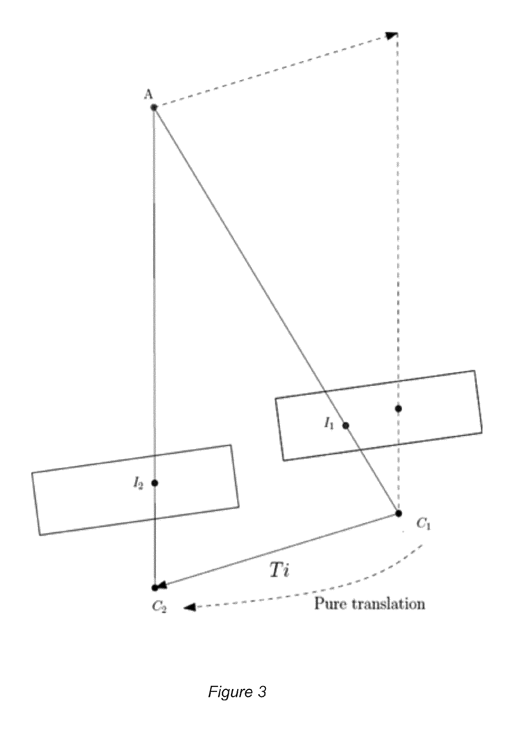
[0041]With reference to FIGS. 1 to 3, a first embodiment of a system 100 according to the invention is shown as a logical diagram of a state machine comprising respective data processing modules.

[0042]A plurality of image frames 101 are continuously obtained from imaging means 105, typically at least one digital camera. A ‘features matching’ module 102 of the system extracts a set of 2D features 201, from each successive image frame 101i, and matches the extracted set with the set of 2D featur...


PUM


Abstract

An improved method and a system are disclosed for recovering a three-dimensional (3D) scene structure from a plurality of two-dimensional (2D) image frames obtained from imaging means. Sets of 2D features are extracted from the image frames, and sets corresponding to successive image frames are matched, such that at least one pair of matched 2D features refers to a same 3D point in a 3D scene captured in 2D in the image frames. A 3D ray is generated by back-projection from each 2D feature, and the generated 3D rays are subjected to an anchor-based minimization process, for determining camera motion parameters and 3D scene points coordinates, thereby recovering a structure of the 3D scene.

Description

FIELD OF THE INVENTION[0001]The present invention relates to a method and system for the estimation of camera motion and the recovery of a 3D scene structure from a plurality of image frames.BACKGROUND OF THE INVENTION[0002]Many methods and systems are known for deriving three-dimensional (‘3D’) information from a plurality of two-dimensional (‘2D’) image frames, for instance photographs. H. Bay, T. Tuytelaars and L. Van Gool (Speeded Up Robust Features, Proceedings of the Ninth European Conference on Computer Vision, 2006) and Lowe (Distinctive Image Features from Scale-Invariant Keypoints, International Journal of Computer Vision, 2:91-110, 2004) teach respective techniques for extracting sets of 2D features from image frames and matching sets respectively extracted from successive frames, such that each pair of matched features refers to a same 3D point in a scene captured in the image frames.[0003]A more widespread use of these methods in image processing applications referred t...

Claims


Application Information

Patent Timeline
IPC IPC(8): G06T7/20
CPCG06T7/2033G06T2207/10016G06T2207/30244G06T7/73G06T7/55G06T7/246
Inventor YOUS, SOFIANEREDMOND, PETERLACEY, GERARD
Owner TRINITY COLLEGE DUBLIN
Learn More