
Flyback power converter and electronic apparatus

Active Publication Date: 2014-05-15
LITE ON TECH CORP
View PDF1 Cites 3 Cited by
  • Summary
  • Abstract
  • Description
  • Claims
  • Application Information

AI Technical Summary

Benefits of technology

The present invention is for a flyback power converter and electronic apparatus that prevents a problem called shooting-through in a continuous conduction mode and reduces stress on the synchronous rectification switch. It also eliminates the need for a signal isolating transmission element, such as a pulse transformer or photocoupler, resulting in higher power density and lower cost.

Problems solved by technology

However, the method is only ensured that the synchronous rectification switch is successfully disabled before a primary side switch switched on in a next switching period under a discontinuous conduction mode.
Although the method is finally able to disable the synchronous rectification switch, there is a short moment when both the primary side switch and the synchronous rectification switch are switched on before the synchronous rectification switch is disabled, and thereby a problem of shoot-through is caused.
As a result, a current stress of the synchronous rectification switch is increased, and a voltage surge of the drain-to-source voltage of the synchronous rectification switch also increases when the synchronous rectification switch is switched off, which increases the voltage stress of the synchronous rectification switch along with a switching consumption; therefore, an overall switching efficiency is lowered, a more cost in high voltage and current stresses of the synchronous rectification switch is caused.

Method used


Image

  • Flyback power converter and electronic apparatus
  • Flyback power converter and electronic apparatus
  • Flyback power converter and electronic apparatus

Examples


Embodiment Construction

[0046]The aforementioned illustrations and following detailed descriptions are exemplary for the purpose of further explaining the scope of the instant disclosure. Other objectives and advantages related to the instant disclosure will be illustrated in the subsequent descriptions and appended drawings. In the drawings, the size and relative sizes of layers and regions may be exaggerated for clarity.

[0047]It will be understood that, although the terms first, second, third, and the like, may be used herein to describe various elements, components, regions, layers and / or sections, these elements, components, regions, layers and / or sections should not be limited by these terms. These terms are only to distinguish one element, component, region, layer or section from another region, layer or section discussed below could be termed a second element, component, region, layer or section without departing from the teachings of the present disclosure. As used herein, the term “and / or” include...


PUM


Abstract

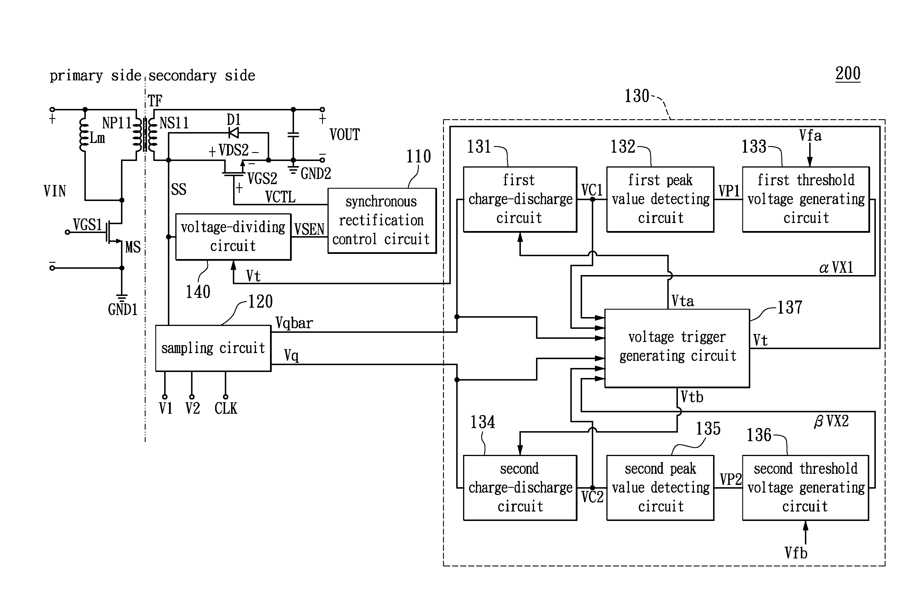
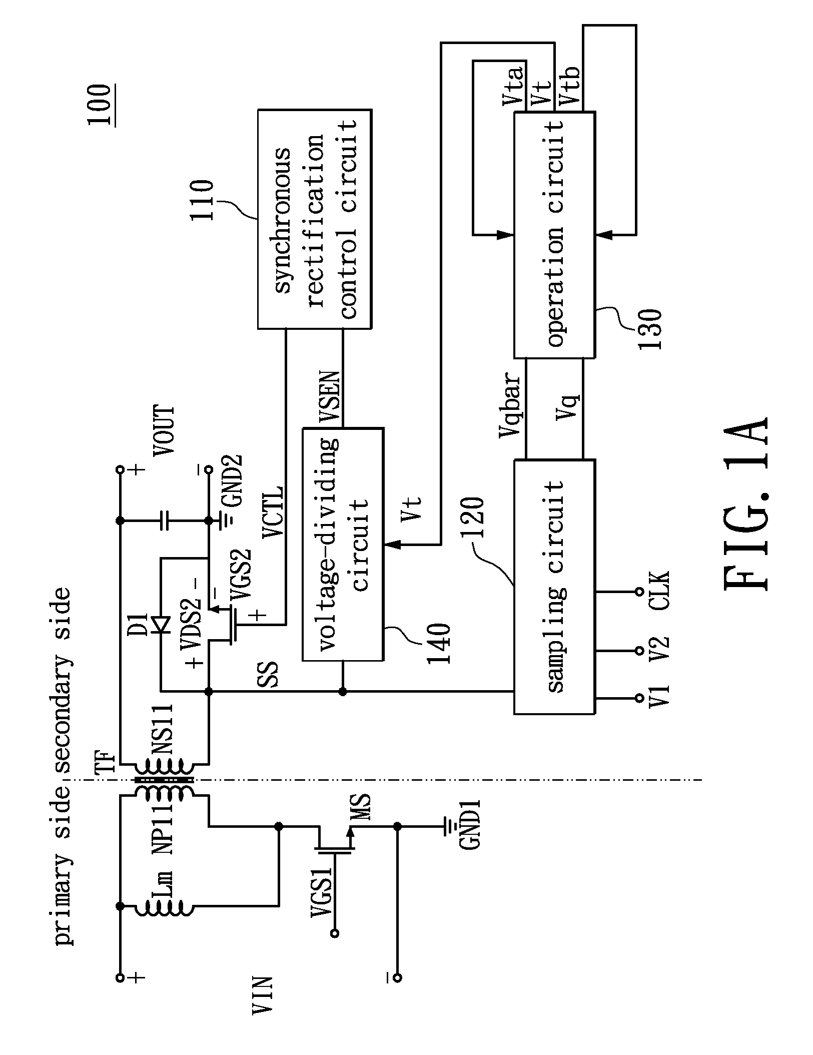
A flyback power converter is disclosed. The flyback power converter includes a voltage transformer, a main switch, a synchronous rectification switch, a synchronous rectification control circuit, a sampling circuit and an operation circuit. A control end of the main switch receives a main switch signal so as to control the main switch. The synchronous rectification control circuit transmits control signal to control end of the synchronous rectification switch according to sensing signal received. The sampling circuit samples the state of the synchronous rectification switch so as to generate first logic signal and second logic signal. The operation circuit executes timing for charging / discharging according to the first and the second logic-signal, so as to output switch cut-off pulse signal to a voltage-dividing circuit. If voltage of the sensing signal is lower than predetermined threshold voltage, the synchronous rectification switch enters into cut-off state according to the control signal.

Description

BACKGROUND OF THE DISCLOSURE[0001]1. Field of the Disclosure[0002]The present disclosure relates to flyback power converter; in particular, to a flyback power converter which is able to perform a synchronous rectification under either a continuous conduction mode or a discontinuous conduction mode.[0003]2. Description of Related Art[0004]In recent years, there is a boost in developing a switching power supply and the switching power supply has been played an extremely important role in computers and other electronic products. In comparison to a traditional power supply, the switching power supply has advantages such as higher stability, simplicity, and efficiency. Among which, a flyback power converter has been broadly used due to a lower cost and a simplified circuit design.[0005]A common method of controlling the flyback power converter in synchronous rectification is to use a synchronous rectification control chip to detect a drain-to-source voltage of a synchronous rectification...

Claims


Application Information

Patent Timeline
IPC IPC(8): H02M3/335
CPCH02M3/33507H02M3/33592Y02B70/10
Inventor LIN, CHUNG-YILAI, WEI-LIEHCHOU, CHU-YILO, YU-KANGCHIU, HUANG-JENLIN, JING-YUAN
Owner LITE ON TECH CORP
Learn More