
Gas analyzer

a gas analyzer and analyzer technology, applied in the field of gas analyzers, can solve problems such as inconsistencies in linearity

Active Publication Date: 2014-05-08
SHIMADZU CORP
View PDF5 Cites 12 Cited by
  • Summary
  • Abstract
  • Description
  • Claims
  • Application Information

AI Technical Summary

Benefits of technology

The present invention is a gas analyzer that can measure the molecular number density of a component in a sample gas with high sensitivity and continuous measurement without interruption. It uses two different detection methods that can measure the molecular number density over a wide range of values. These methods are called harmonic synchronous detection and direct absorption spectrometry. The gas analyzer captures signals from both methods simultaneously and selects the most suitable method based on the molecular number density of the component being measured. The invention also includes a laser control system that can change the wavelength of the laser light to measure the molecular number density of a component that does not absorb the light. This laser control system is effective for measuring gas with a high molecular number density, such as moisture in a gas. The gas analyzer has expanded the range of molecular number density that can be measured and holds measurement continuity.

Problems solved by technology

As thusly described, the harmonic synchronous detection method has high sensitivity, but linearity inconsistencies occur when the molecular number density is high.

Method used


Image

  • Gas analyzer
  • Gas analyzer
  • Gas analyzer

Examples


example 1

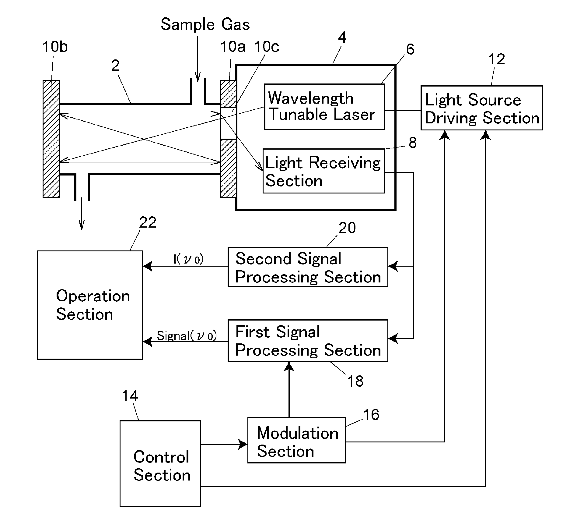
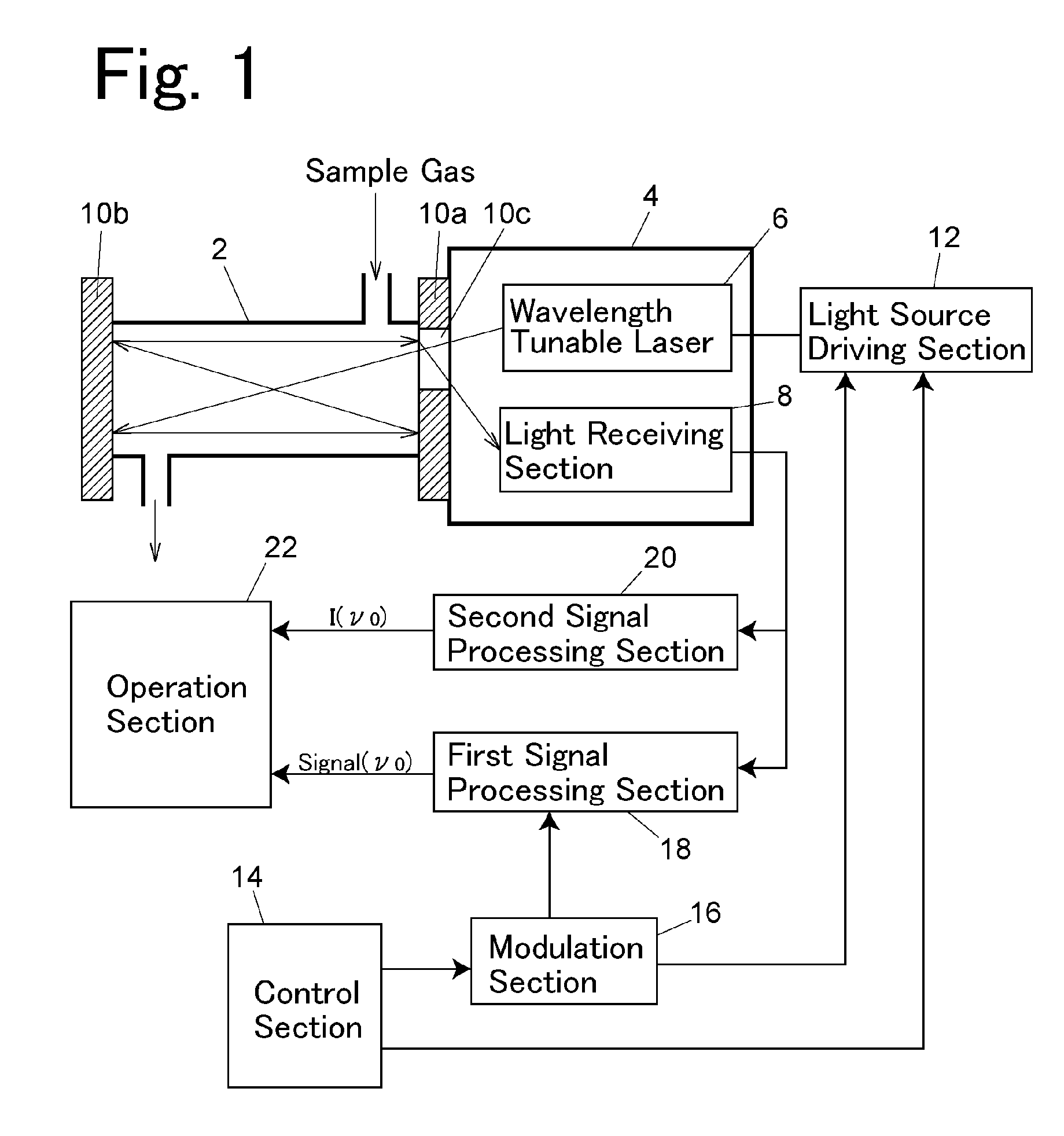
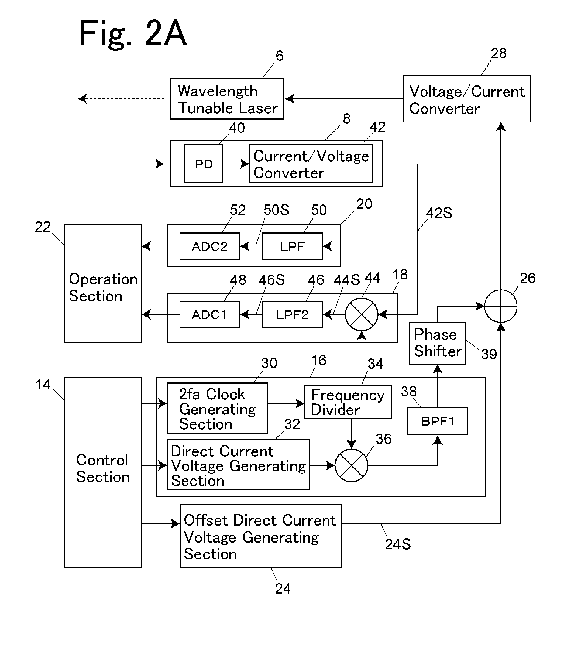
[0048]A first example of the present invention will be described using FIGS. 1, 2A and 2B. A gas analyzer of the present example is a moisture measuring device for measuring a molecular number density of moisture in a component to be measured.

[0049]As shown in FIG. 1, the gas analyzer of the present example is provided with a sample cell 2 arranged in a substantially horizontal direction on a gas flow channel where a sample gas is allowed to flow downward from the above. Two mutually opposing reflectors 10a, 10b are provided on right and left opening ends of the sample cell 2. A part of the one reflector 10a is provided with a transparent window 10c which is, for example, made up of quartz so that only light is passable therethrough, and on the outside of the sample cell 2, with the reflector 10a sandwiched between the outside and the sample cell 2, an optical chamber 4 is mounted which has a substantially sealed structure and an atmosphere of substantially atmospheric pressure. Ins...

example 2

[0067]Next, a second example will be described using FIGS. 4A to 4F. A configuration of the entire device of the gas analyzer of the present example is similar to that of FIG. 1, but in the present example, a signal processing system is partially different since a light frequency of laser light is scanned. Hereinafter, a description will be provided with a focus on a different portion from the first example.

[0068]In the present example, a drive current of the wavelength tunable laser 6 is changed by means of, for example, a sawtooth wave with a frequency fb that is lower than the frequency fa, thereby scanning an oscillating frequency of laser light. Since the oscillating frequency of laser light is scanned, it is not necessary to highly accurately set the oscillating frequency of laser light to a center frequency of an absorption line of the component to be measured as in Example 1, and since scanning can be continuously performed any number of times, it is possible to improve an S...

example 3

[0085]Next, a third example of the gas analyzer will be described using FIGS. 8A and 8B. In the present example, it is configured such that part of laser light emitted from the wavelength tunable laser 6 is split from laser light, with which the sample cell 2 is irradiated, by a beam splitter 7 and the split light is then led to a light receiving section 8b side without being allowed to pass through the sample cell 2. In addition to a photodiode 40a for detecting laser light allowed to pass through the inside of the sample cell 2 and a current / voltage converter 42a that converts a current signal of the photodiode 40a to a voltage signal, the light receiving section 8b is provided with a photodiode 40b for detecting laser light not allowed to pass through the inside of the sample cell 2 and a current / voltage converter 42b, and simultaneously detects the laser light allowed to pass through the inside of the sample cell 2 and the laser light not allowed to pass therethrough in separate...


PUM

PropertyMeasurementUnit
total pressureaaaaaaaaaa
time constantaaaaaaaaaa

Abstract

A gas analyzer includes: a first signal processing section for synchronously detecting a light detection signal at a frequency being an integral multiple of a modulation frequency fa of a laser light, to detect a harmonic signal intensity Signal(ν) by a harmonic synchronous detection method; a second signal processing section for capturing a light detection signal and cutting off a frequency component not smaller than the frequency fa to detect a light intensity signal I(ν) at a specific light frequency absorbed by a component to be measured in a sample gas; and an operation section. The operation section includes a first operation means for calculating a density c of the component from the harmonic signal intensity Signal(ν) and a reference light intensity signal I0(ν) and a second operation means for calculating the density c from the light intensity signal I(ν) and the reference light intensity signal I0(ν).

Description

BACKGROUND OF THE INVENTION[0001]1. Field of the Invention[0002]The present invention relates to a gas analyzer for measuring a molecular number density of a component to be measured in a sample gas by means of absorption of laser gas.[0003]2. Description of the Related Art[0004]In recent years, as a method for measuring a molecular number density of a specific gas in a vapor, laser absorption spectroscopy by means of absorption of laser light has been proposed (e.g., Unexamined Japanese Patent Publication No. 5-099845). This method is to irradiate a sample cell, where a sample gas has been introduced, with laser light with a predetermined frequency and to analyze the transmitted laser light, to derive a molecular number density of a component to be measured in the sample gas from the degree of absorption in the component to be measured. This device is a non-contact type where a light receiving section as a sensor is not in contact with the sample gas, thereby having an advantage of...

Claims


Application Information

Patent Timeline
Patent Type & Authority Applications(United States)
IPC IPC(8): G01N21/61
CPCG01J3/4338G01J2001/4242G01N21/031G01N21/05G01N21/3504G01N21/39G01N2021/399
Inventor OTERA, FUMIAKI
Owner SHIMADZU CORP
Learn More