
Blast resistant pipe protection system and method

a technology of blast-resistant pipes and pipe protection, which is applied in the direction of pipe protection, pipe protection, pipe damage/wear prevention, etc., can solve the problems of ineffective physical protection of pipelines from close proximity explosive attacks, and limited attention to energy security in this case, specifically pipeline security, and achieve the effect of protecting pipelines from damage/wear

Inactive Publication Date: 2014-05-08
ROK INVESTMENT GROUP
View PDF10 Cites 5 Cited by
  • Summary
  • Abstract
  • Description
  • Claims
  • Application Information

AI Technical Summary

Benefits of technology

The present invention relates to a system and method for protecting pipes, including over or under land transmission pipelines and building utility pipes, from blast resistance. The system includes an energy absorbing inner matrix, a outer wrap of fire-resistant foil, and a blast-resistant material between the inner and outer wraps. The blast-resistant material consists of Purlite, which is contained in multiple bags and arranged circumferentially around the pipe. The energy absorbing inner matrix is made up of a polymeric annulus and fiberglass half-pipes. The system has a minimum blast resistance of 50 pounds of TNT at a distance of 10 feet. The technical effects of this invention include improved protection against blast resistance and minimization of damage to pipelines in the event of a blast.

Problems solved by technology

Prior to the 2001 attacks on the World Trade Center in New York, worldwide attention on energy security, in this case, specifically pipeline security, was extremely limited.
It is not as effective at physically protecting a pipeline from a close proximity explosive attack, due to the simple fact that the pipeline still gets deformed and / or penetrated.

Method used


Image

  • Blast resistant pipe protection system and method
  • Blast resistant pipe protection system and method
  • Blast resistant pipe protection system and method

Examples


example 1

[0056]This Example serves to illustrate blast resistance of the blast protective system and method.

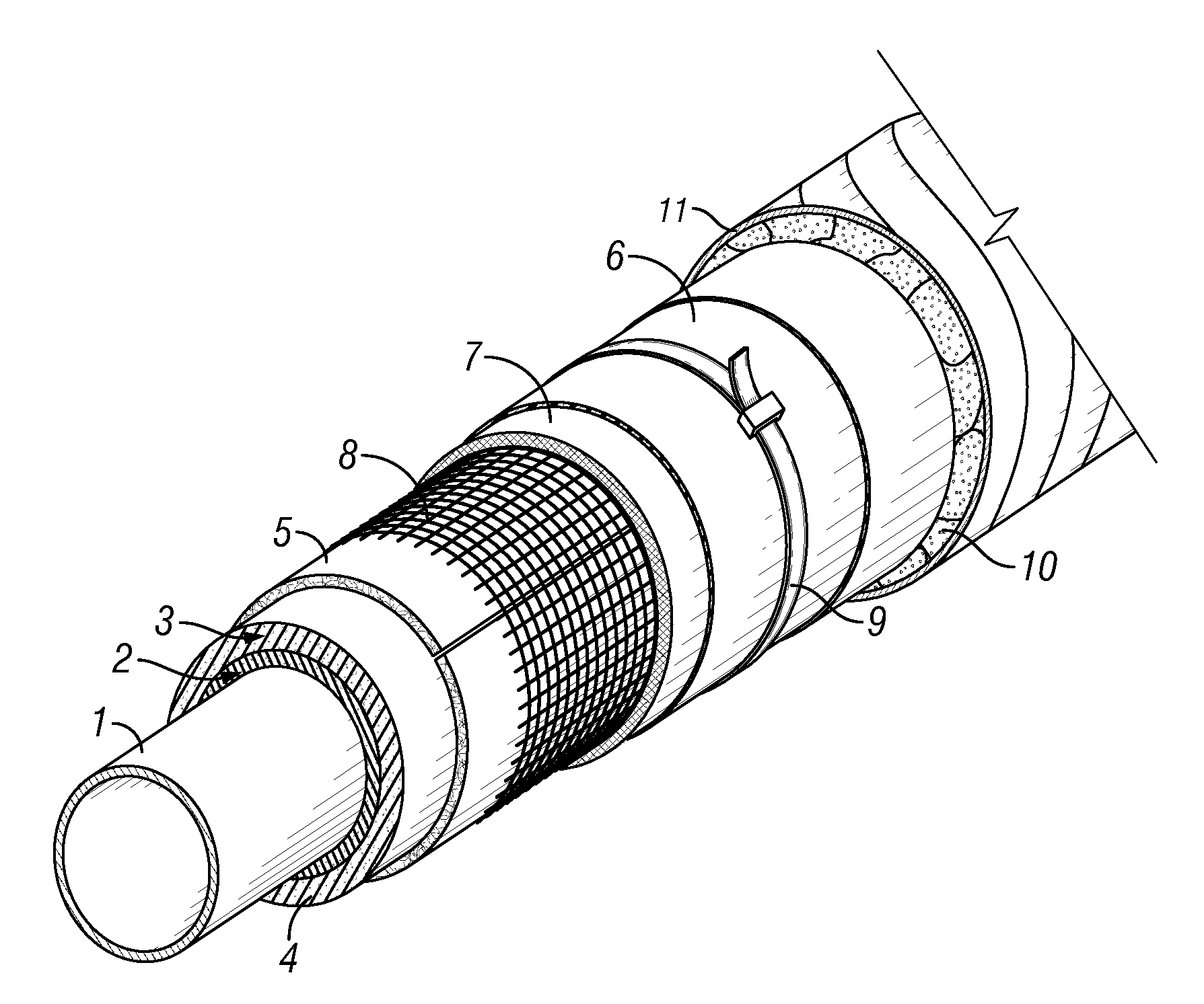
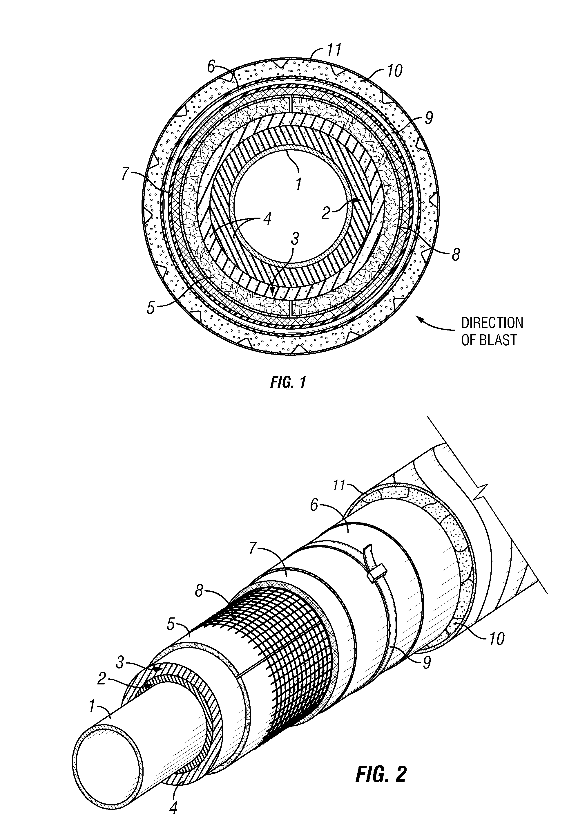
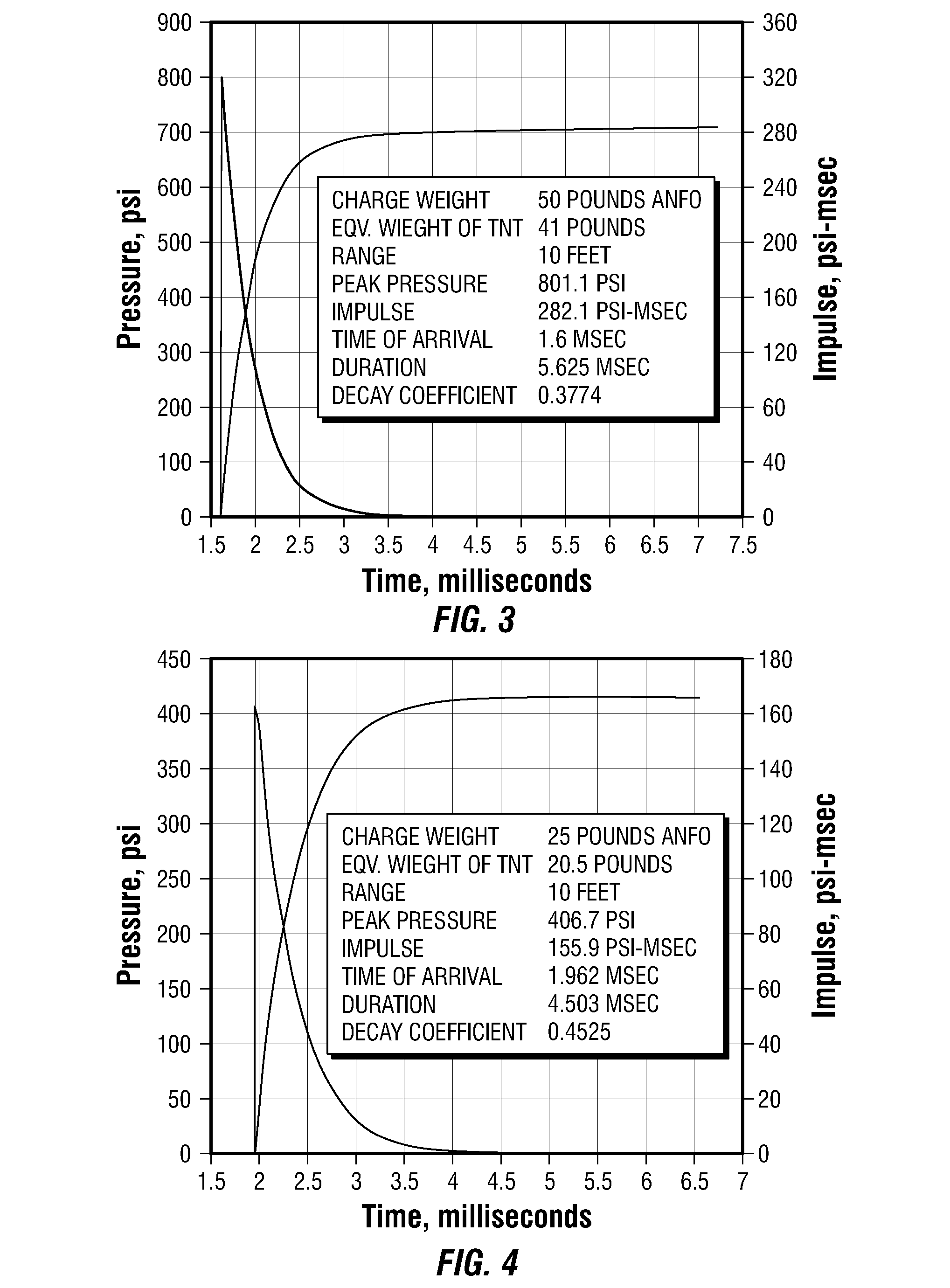
[0057]In a typical procedure, a system as depicted in FIGS. 1 and 2, as described in the accompanying description above, was applied to a pipe. The charge weight was about 50 pounds of ANFO. The equivalent weight of TNT was 41 pounds. The range was about 10 feet. The peak pressure was 801.1 psi. The impulse was 282.1 psi-msec. The time of arrival was 1.6 msec. The duration was 5.625 msec. The decay coefficient was 0.374. Pressure and impulse as a function of time, illustrating reflected pressure for a hemispherical surface burst, are depicted in FIG. 3.

example 2

[0058]This Example serves to further illustrate blast resistance of the blast protective system and method.

[0059]In a typical procedure, a system as depicted in FIGS. 1 and 2, as described in the accompanying description above, was applied to a pipe. The charge weight was 25 pounds of ANFO. The equivalent weight of TNT was 20.5 pounds. The range was about 10 feet. The peak pressure was 406.7 psi. The impulse was 169.9 psi-msec. The time of arrival was 1.962 msec. The duration was 4.580 msec. The decay coefficient was 0.4525. Pressure and impulse as a function of time, illustrating reflected pressure for a hemispherical surface burst, are depicted in FIG. 4.

example 3

[0060]This Example serves to further illustrate blast resistance of the blast protective system and method.

[0061]In a typical procedure, a system as depicted in FIGS. 1 and 2, as described in the accompanying description above, was applied to a pipe. The blast load resistance desired for a water main needed to be Peak pressure @ 52.2 psi-msec (P=defined as blast overpressure) and Impulse @ 73.7 psi (I is defined as impulse wave pressure). According to South West Research, one of the leading blast and explosive testing engineering firms in the U.S., an illustrative implementation of the invention only needed 9 pounds of TNT to achieve the requirements. In the end, WinTec exceeded the test requirements by a factor of over 15 times.


PUM


Abstract

The present invention is directed to generally to protection of structures from explosives, and specifically to a blast resistant pipe protection system and method for using same. The present invention is directed to a system and method for protecting a pipe. In some embodiments, the present invention is directed to a system for protecting a pipe, comprising an energy absorbing inner matrix bound to the pipe; an outer wrap comprising fire resistant foil; and a blast resistant material disposed between the inner matrix and the outer wrap, wherein the blast resistant material comprises Purlite. In some embodiments, the present invention is directed to a method for protecting a pipe comprises binding an energy absorbing inner matrix to the pipe; disposing Purlite around the inner matrix; and wrapping the Purlite with fire resistant foil.

Description

CROSS-REFERENCE TO RELATED APPLICATIONS[0001]This Application for Patent claims priority to U.S. Provisional Patent Application Ser. No. 61 / 500530, filed Jun. 23, 2011.FIELD OF THE INVENTION[0002]The present invention relates generally to protection of structures from explosives, and specifically to a blast resistant pipe protection system and method for using same.BACKGROUND OF THE INVENTION[0003]According to the U.S. Government's security agency, TSA, there are 161,189 miles of hazardous liquid pipelines and 309,503 miles of Natural Gas pipelines and 1.9 million miles of Natural Gas distribution lines in the U.S. America's enemies have concluded that the most effective way to accomplish their avowed goals of destroying our economic base and target the most vulnerable targets that could effect the greatest disruption to the U.S. economy, would involve attacks to our energy transmission pipelines. The history of man made systems that can or might offer some form of explosive and / or ...

Claims


Application Information

Patent Timeline
Patent Type & Authority Applications(United States)
IPC IPC(8): F16L57/00
CPCF16L57/00F16L9/14
Inventor HENRY, JAMES JACKSON MILHAM
Owner ROK INVESTMENT GROUP
Learn More