Dual Fuel Injection Valve

a fuel injection valve and dual technology, applied in the direction of engines, mechanical equipment, machines/engines, etc., can solve the problems of limiting the amount of diesel that can be substituted with natural gas and/or the compression ratio, the pre-mixed homogeneous mixture of natural gas and air becomes too lean to burn, and the engine that introduces natural gas by fumigation cannot match the power, performance and efficiency of equivalently-sized diesel engines

Active Publication Date: 2014-05-08
WESTPORT FUEL SYST CANADA INC
View PDF0 Cites 26 Cited by
  • Summary
  • Abstract
  • Description
  • Claims
  • Application Information

AI Technical Summary

Problems solved by technology

However, pre-mixing natural gas and air in this manner limits the amount of diesel that can be substituted with natural gas and / or the compression ratio that can be safely used, because fumigating too much natural gas can result in engine knock, which is premature detonation of the fuel that can damage the engine.
Another disadvantage of fumigated engines is that under low load engine operating conditions, the pre-mixed homogeneous mixture of natural gas and air becomes too lean to burn.
Consequently, engines that introduce natural gas by fumigation have not been able to match the power, performance, and efficiency of equivalently-sized diesel engines.
Also, at low load operating conditions because the fuel is not pre-mixed, and instead burns in a diffusion combustion mode, the same challenges that fumigated engines have with these operating conditions are not encountered with HPDI gaseous-fuelled engines.
A challenge associated with the operational principle underlying pilot-ignited HPDI gaseous-fuelled engines is that means must be provided for injecting the gaseous fuel and the pilot fuel directly into the combustion chamber.
Modern internal combustion engines can typically have two intake valves and two exhaust valves and these valves occupy a substantial amount of the space in the cylinder head above the combustion chamber.
Consequently, it can be a problem finding enough space in the cylinder head to install a second fuel injector.
A problem observed with pilot-ignited HPDI engines employing concentric gaseous and liquid fuel injection valves is that there can be periodic variations in engine speed and NOx emissions.
The amplitude of these variations can be particularly large when the load is small.
These variable conditions can lead to irregular engine operation.
Also, it was believed that it is best to allow the inner pilot fuel valve body to rotate freely to better adapt to the different characteristics of each cylinder in a multi-cylinder engine, and it was believed that a fixed interlace angle would be difficult to optimize for every cylinder.
The experiments have shown that unstable engine speed can be attributed to variations in combustion quality that are believed to be caused by variations in the interlace angle especially when there is an equal number of gaseous and pilot fuel orifices.
While the solution taught by the '192 patent might solve the problem for an engine with concentric gaseous and liquid fuel injection valves positioned in the center of the cylinder, it would not be a desirable solution for all engine configurations.

Method used


Image

  • Dual Fuel Injection Valve
  • Dual Fuel Injection Valve
  • Dual Fuel Injection Valve

Examples


Embodiment Construction

)

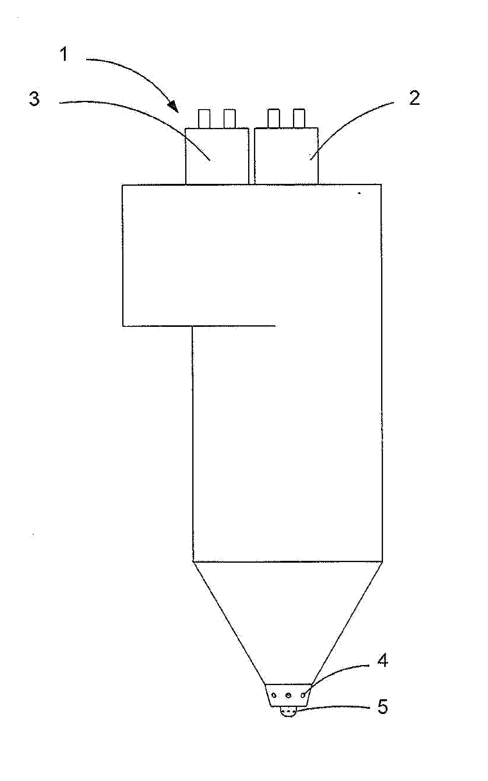
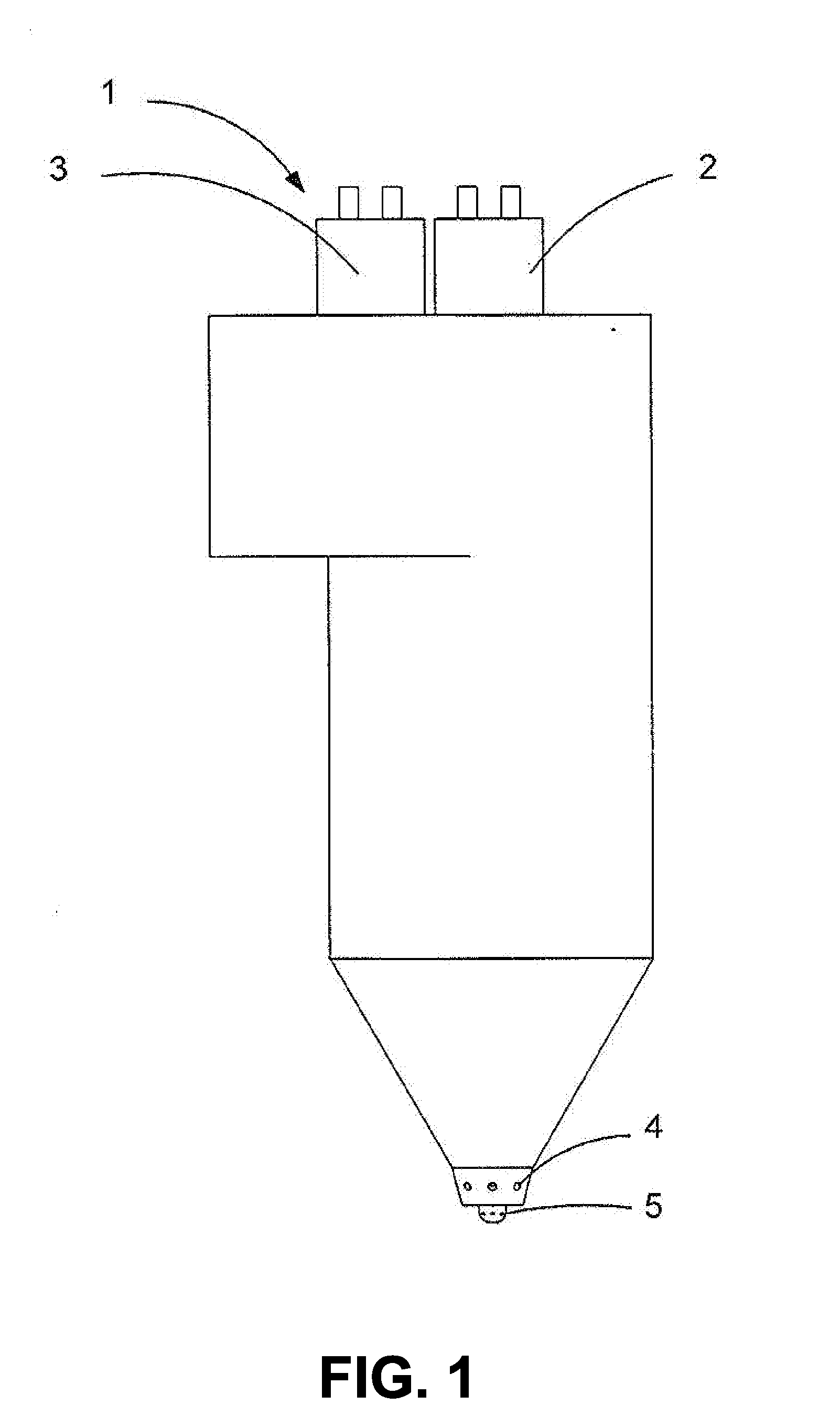
[0053]The disclosed dual fuel injection valve is capable of independently and separately injecting two different fuels into the combustion chamber of an internal combustion engine. Each of the two fuels is injected into the combustion chamber through separate orifices that communicate directly to the combustion chamber. The dual fuel injection valve can provide independent control of the injection timing and fuel quantity for each of the two fuels. A first fuel can be a gaseous fuel and a second fuel can be a pilot fuel, preferably a liquid fuel that will auto-ignite in a compression ignition engine more readily than the gaseous fuel. The injection of the two fuels can be controlled such that, for example, at least some of the gaseous fuel is injected into the combustion chamber sequentially after the liquid fuel. Preferably, the gaseous fuel comprises more than 90% of the fuel consumed by the engine measured on an energy basis.

[0054]In preferred embodiments, the gaseous fuel is na...


PUM


Abstract

A dual fuel injection valve with concentric needles comprises an inner needle and an outer needle surrounding the inner needle, both needles being located inside the injection valve body. The valve is provided with a first set and a second set of orifices for separately injecting two different fuels directly into the combustion chamber of an internal combustion engine. The outer needle is fixed against rotation with respect to the injection valve body such that an interlace angle between the centerlines of the first series of orifices and second series of orifices is set at different predetermined angles to reduce methane emissions.

Description

CROSS-REFERENCE TO RELATED APPLICATIONS[0001]This application is a continuation of International Application No. PCT / CA2012 / 050348 having an international filing date of May 28, 2012 entitled “Dual Fuel Injection Valve”. The '348 international application claimed priority benefits, in turn, from Canadian Patent Application No. 2,743,043 filed on Jun. 14, 2011. The '348 international application is hereby incorporated by reference herein in its entirety.FIELD OF THE INVENTION[0002]The present invention relates to a dual fuel injection valve with concentric needles for separately injecting two different fuels into the combustion chamber of an internal combustion engine.BACKGROUND OF THE INVENTION[0003]Because of its ready availability, low cost and potential for reducing particulate emissions, natural gas is gaining acceptance as a fuel for internal combustion engines. Natural gas is only one example of a gaseous fuel with such benefits that can replace diesel in internal combustion e...

Claims


Application Information

Patent Timeline
Patent Type & Authority Applications(United States)
IPC IPC(8): F02M21/02F02M63/00
CPCF02M21/0275F02M63/007F02D19/10F02M43/04F02M45/086F02M47/027F02D19/0644F02D19/0652F02D19/0694F02M2200/46F02M2200/8015F02M2200/852F02M61/182F02M61/14Y02T10/30
Inventor WICKSTONE, MICHAEL C.HILL, PHILIP G.HUANG, JIANMUNSHI, SANDEEP
Owner WESTPORT FUEL SYST CANADA INC
Why Eureka
Try Eureka