
Method of manufacturing a semiconductor device

a manufacturing method and semiconductor technology, applied in semiconductor/solid-state device manufacturing, basic electric elements, electric devices, etc., can solve the problems of increasing the difficulty of maintaining or improving the transistor performance, the deficiency of spacer patterning technology, and the near-limitation of photolithography, so as to achieve the effect of improving the spacer patterning technology

Inactive Publication Date: 2014-05-01
INST OF MICROELECTRONICS CHINESE ACAD OF SCI
View PDF3 Cites 2 Cited by
  • Summary
  • Abstract
  • Description
  • Claims
  • Application Information

AI Technical Summary

Benefits of technology

The present invention is a method for manufacturing transistors that improves the technology used to pattern the space between the transistors' gates. This method uses a technology similar to a new process called gate-last, which avoids the drawbacks of existing methods. The invention has advantages such as forming a spacer mask with a more consistent and accurate shape, increasing the likelihood of a successful masking process. This results in better performance and more reliable performance of the transistor.

Problems solved by technology

Ever since the semiconductor integrated circuit technology has entered into the technical node of a feature size of 90 nm, it becomes increasingly challenging to maintain or improve the transistor performance.
In order to conform to the Moore's Law, it is required that the device feature size should be reduced continuously, but the conventional 193 nm photolithography has almost reached its limit, while other technologies like EUV and electron beam are still far from business application.
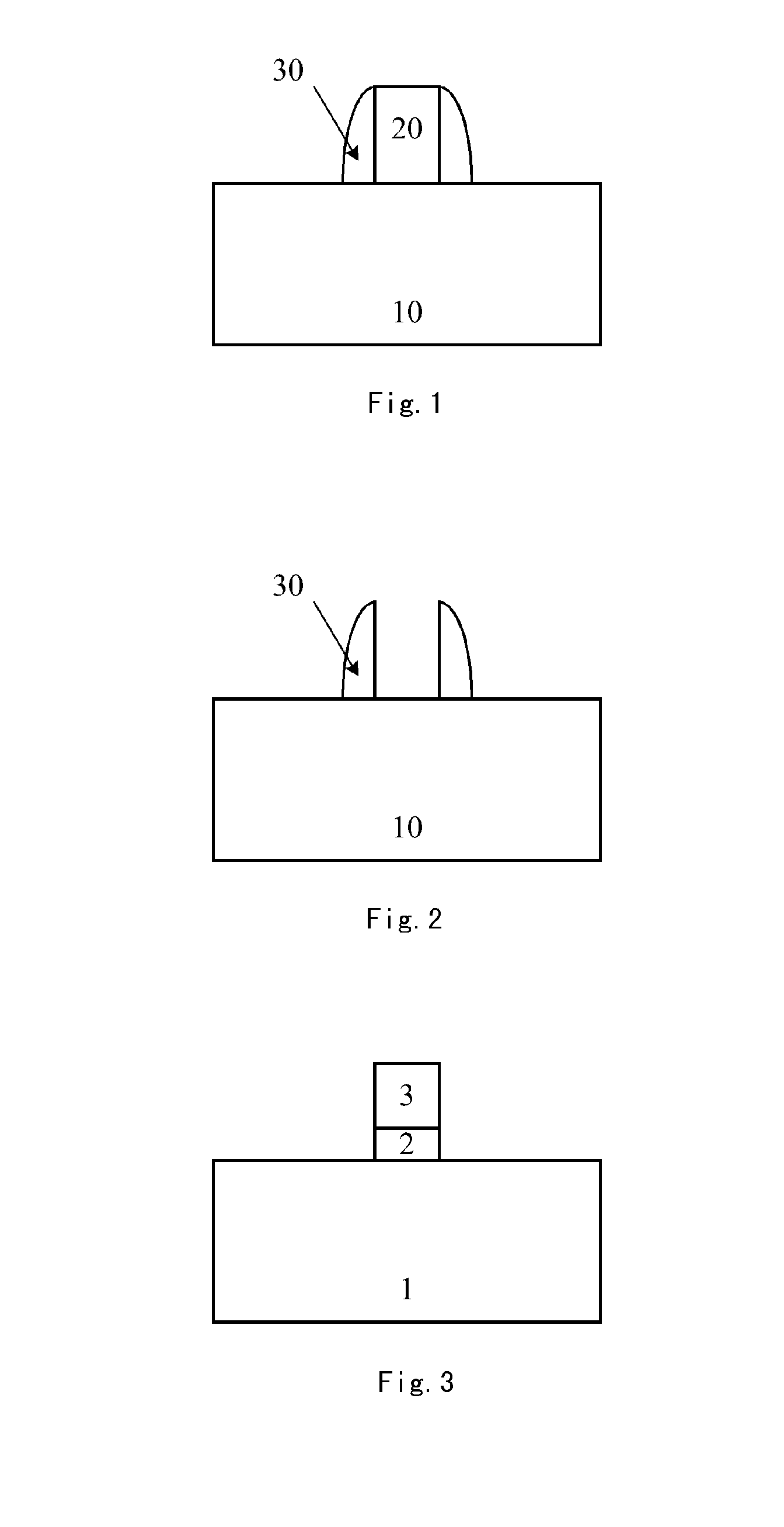
However, the spacer patterning technology also has a distinct deficiency, namely, the profile of the spacer is not laterally symmetric, thus the shape formed by the subsequent etching is not laterally symmetric.

Method used


Image

  • Method of manufacturing a semiconductor device
  • Method of manufacturing a semiconductor device
  • Method of manufacturing a semiconductor device

Examples


Embodiment Construction

[0021]The present invention is described below through the specific embodiments shown in the figures, but it shall be understood that these descriptions are exemplary and are not intended to limit the scope of the present invention. In addition, in the text below, descriptions about the known structures and techniques are omitted to avoid unnecessarily confusing the concept of the present invention.

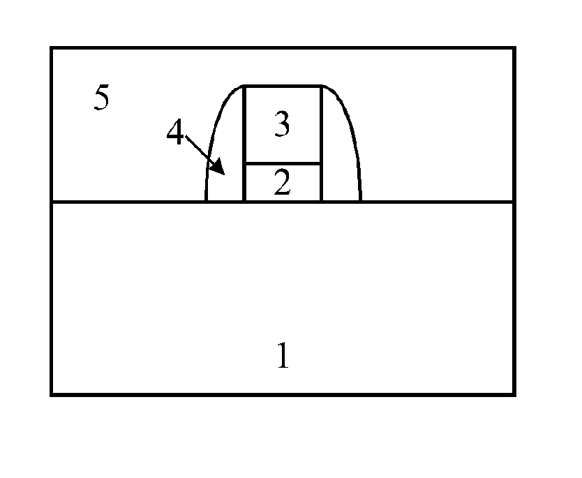
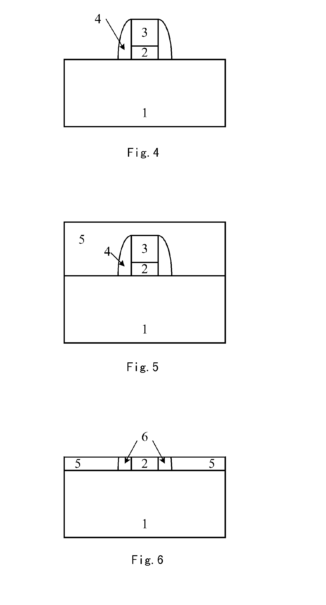
[0022]The present invention provides a semiconductor device manufacturing method, in particular relates to improving the spacer patterning technology by means of a sacrificial layer and a barrier layer, which avoids the deficiency in the existing spacer patterning technology. Now the semiconductor device manufacturing method provided by the present invention will be described in details with reference to FIGS. 3-7.

[0023]First, referring to FIG. 3, a barrier material layer and a sacrificial material layer (not shown) are deposited in sequence on a semiconductor substrate 1 and are patterne...


PUM


Abstract

The present invention relates to a method of manufacturing a semiconductor device for improving the spacer mask. In the present invention, a barrier layer and a sacrificial layer are formed, and the portions of the upper part of the spacer whose left and right sides differ greatly are ground away to leave the portion similar to a rectangle at the bottom of the spacer, which is used as the mask to perform the subsequent spacer masking technology. Thus the undesirable influences to the subsequent etching caused by the asymmetric profile of the spacer can be reduced as much as possible.

Description

CROSS REFERENCE[0001]This application is a National Phase application of, and claims priority to, PCT Application No. PCT / CN2012 / 001380, filed on Oct. 12 , 2012, entitled ‘METHOD OF MANUFACTURING A SEMICONDUCTOR DEVICE’, which claimed priority to Chinese Application No. CN 201210283268.1, filed on Aug. 9, 2012. Both the PCT Application and Chinese Application are incorporated herein by reference in their entireties.FIELD OF THE INVENTION[0002]The present invention relates to the field of manufacture of a semiconductor integrated circuit, in particular to a transistor manufacturing method that uses a sacrificial layer and a barrier layer to improve the spacer patterning technology.BACKGROUND OF THE INVENTION[0003]Ever since the semiconductor integrated circuit technology has entered into the technical node of a feature size of 90 nm, it becomes increasingly challenging to maintain or improve the transistor performance. In order to conform to the Moore's Law, it is required that the d...

Claims


Application Information

Patent Timeline
Patent Type & Authority Applications(United States)
IPC IPC(8): H01L21/3213
CPCH01L21/0337H01L21/32139H01L21/0338H01L21/28132H01L21/2815H01L21/28123
Inventor QIN, CHANGLIANGYIN, HUAXIANG
Owner INST OF MICROELECTRONICS CHINESE ACAD OF SCI
Learn More