LED directional lighting system with light intensity controller

a technology of led directional lighting and light intensity controller, which is applied in the field of landscape lighting systems and light fixtures, can solve the problems of uneven illumination levels, black unlit holes, hot spots, etc., and achieve the effects of reducing the wobble between the mating of the two parts, rapid advancement of led technology, and ensuring flexibility for installers

Active Publication Date: 2014-05-01
MIND HEAD
View PDF11 Cites 35 Cited by
  • Summary
  • Abstract
  • Description
  • Claims
  • Application Information

AI Technical Summary

Benefits of technology

The patent text describes a lighting fixture that allows for adjustable lighting intensity and glare control. The fixture includes a light engine slug that can be adjusted in its position relative to the inner ring of an upper knuckle. This design allows for additional space when adding lenses or other optics to the fixture. The adjustable position of the light engine slug can be locked in place with a set screw, and the fixture can be rotated to align a specific light pattern. The technical effects of this invention include improved control over lighting intensity and glare control, as well as flexibility in adding optics and other accessories to the fixture.

Problems solved by technology

Bad lighting designs result in hot spots, black unlit holes, uneven illumination levels, overly bright spots and under-illuminated areas.
The extreme differences between the contrasting light levels fatigue the eye and results in landscape lighting that is uncomfortable to look at.

Method used


Image

  • LED directional lighting system with light intensity controller
  • LED directional lighting system with light intensity controller
  • LED directional lighting system with light intensity controller

Examples


Embodiment Construction

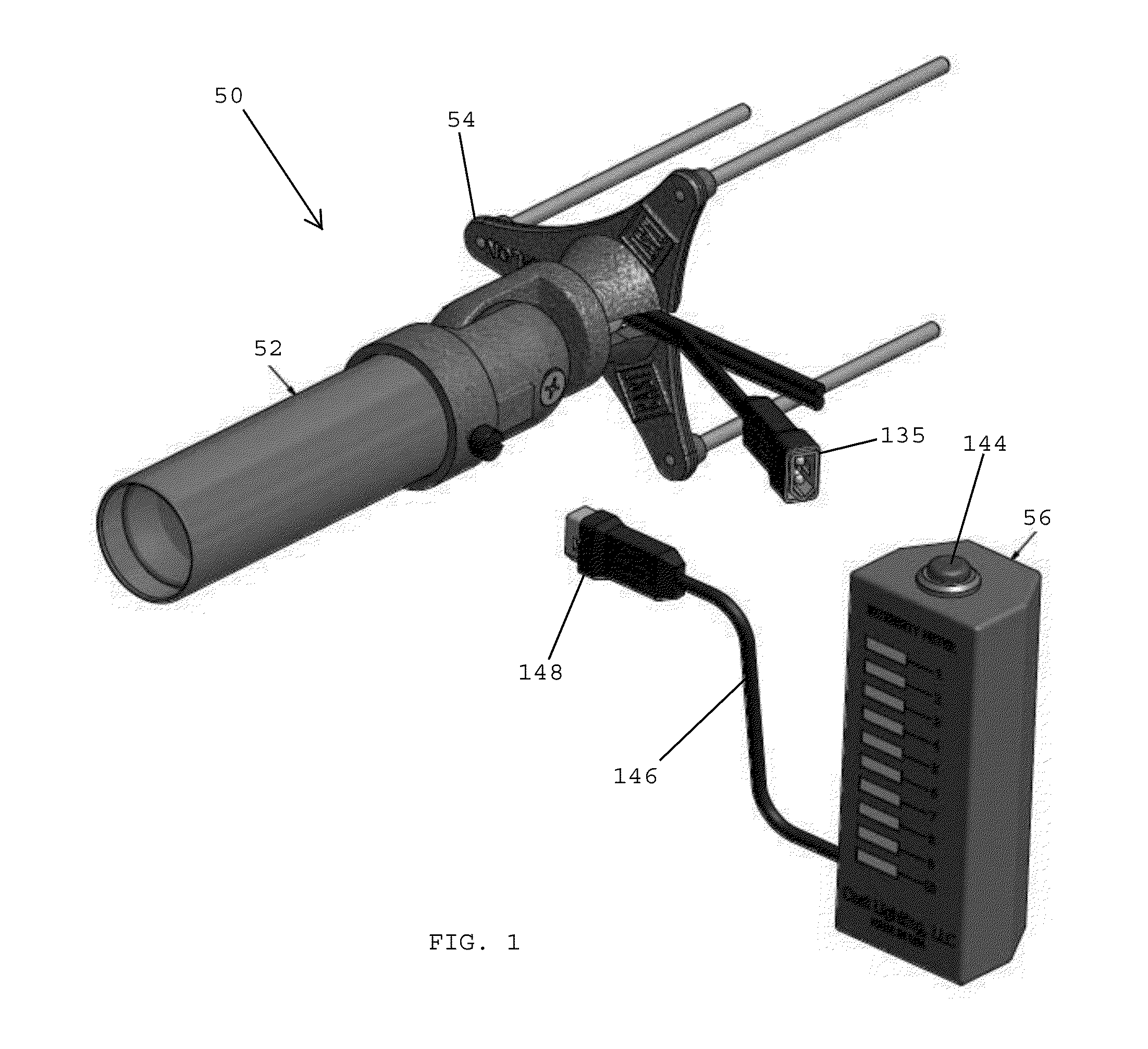
[0075]Referring to FIG. 1, in one embodiment, a landscape lighting system 50 preferably includes a light fixture 52 having a base 54. The lighting system 50 desirably includes a light intensity controller 56 that may be connected with the light fixture 52 for controlling the intensity of the light generated by the light fixture.

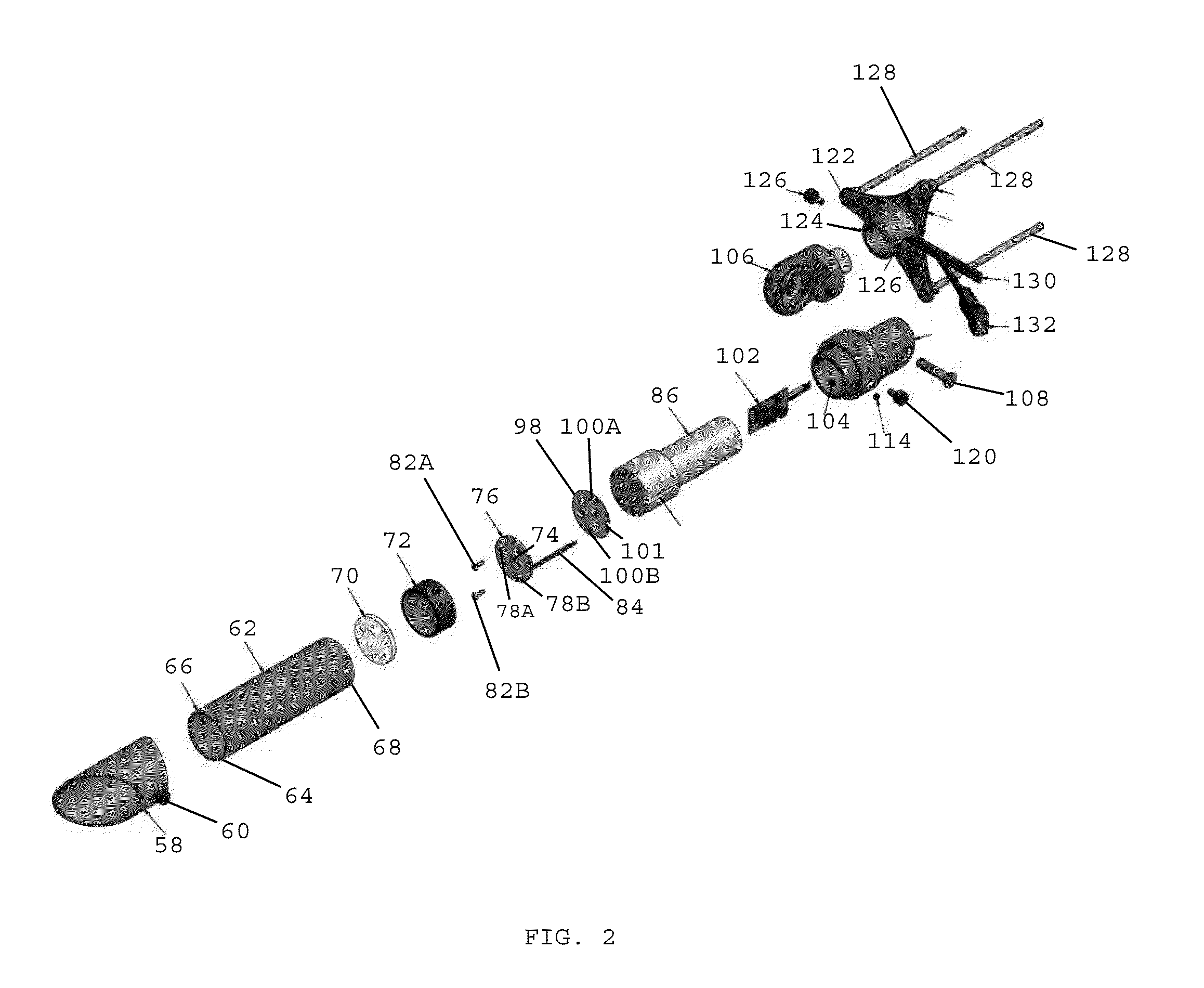
[0076]Referring to FIG. 2, in one embodiment, the light fixture 52 preferably includes a glare shield 58, such as a reversible glare shield, having a rotatable thumb screw 60. The glare shield 58 is preferably made of a non-ferrous metal such as copper, aluminum, or brass. In one preferred embodiment, the glare shield 58 is made of extruded copper. In one embodiment, a non-glossy coating, such as a Teflon PTFE black matte, no-gloss coating is applied over the inside surface of the glare shield to reduce glare.

[0077]In one embodiment, the light fixture 52 desirably includes a shroud 62 having a leading end 64 with a rolled edge 66 and a trailing end 68. In one...


PUM


Abstract

A landscape lighting system includes a light engine slug, an LED secured to a leading end of the light engine slug, an LED driver for controlling operation of the LED, wherein the LED driver is spaced from the LED, and conductive wires electrically interconnecting the LED driver and the LED. The lighting system includes a plurality of interchangeable light diverting elements adapted to be secured over the LED. Each of the light diverting elements has a unique light diversion angle associated therewith, whereby only one of the light diverting elements is secured over the LED at any one time. The landscape lighting system includes a light intensity controller in communication with the LED driver. The light intensity controller includes a control element that enables an operator to selectively increase and decrease the intensity of the light generated by the LED.

Description

CROSS REFERENCE TO RELATED APPLICATIONS[0001]The present application claims benefit of U.S. Provisional Application No. 61 / 718,852, filed Oct. 26, 2012, and U.S. Provisional Application No. 61 / 789,449, filed Mar. 15, 2013, the disclosures of which are hereby incorporated by reference herein.BACKGROUND OF THE INVENTION[0002]1. Field of the Invention[0003]The present application is generally related to lighting and is more specifically related to landscape lighting systems and light fixtures used to provide landscape lighting.[0004]2. Description of the Related Art[0005]Landscape lighting designers and installers typically utilize various lighting techniques to create a decorative landscape lighting design for a property owner. The selected landscape lighting design matches the property owner's preferences, desires, and tastes, and the theme that exists for the property. Property owner preferences may include safety, security and the beautification of the property's outdoor landscape....

Claims


Application Information

Patent Timeline
IPC IPC(8): F21S6/00H05B44/00
CPCF21S6/004F21S8/083F21V21/0824F21Y2101/00F21K9/60F21Y2115/10F21V23/006H05B47/195H05B45/10F21V29/70F21V11/16F21V17/002F21V21/30F21W2131/109F21S8/032F21V1/08F21V21/14F21V23/0435F21W2131/10F21V9/08
Inventor BEAUSOLEIL, DAVID M.
Owner MIND HEAD
Why Eureka
Try Eureka