Eureka AIR delivers breakthrough ideas for toughest innovation challenges, trusted by R&D personnel around the world.

Process for enabling carbon-capture from existing combustion processes

a technology of existing combustion processes and carbon capture, which is applied in the direction of separation processes, emission prevention, lighting and heating apparatus, etc., can solve the problems of obtaining oxygen in the operation of oxygen-fuel combustion processes, the upper limit of cosub>2 /sub>could be captured, and the inability to size an amine scrubber to process the entire stream, etc., to achieve the effect of improving feed

Active Publication Date: 2014-03-20
PHILLIPS 66 CO
View PDF5 Cites 14 Cited by
  • Summary
  • Abstract
  • Description
  • Claims
  • Application Information

AI Technical Summary

Benefits of technology

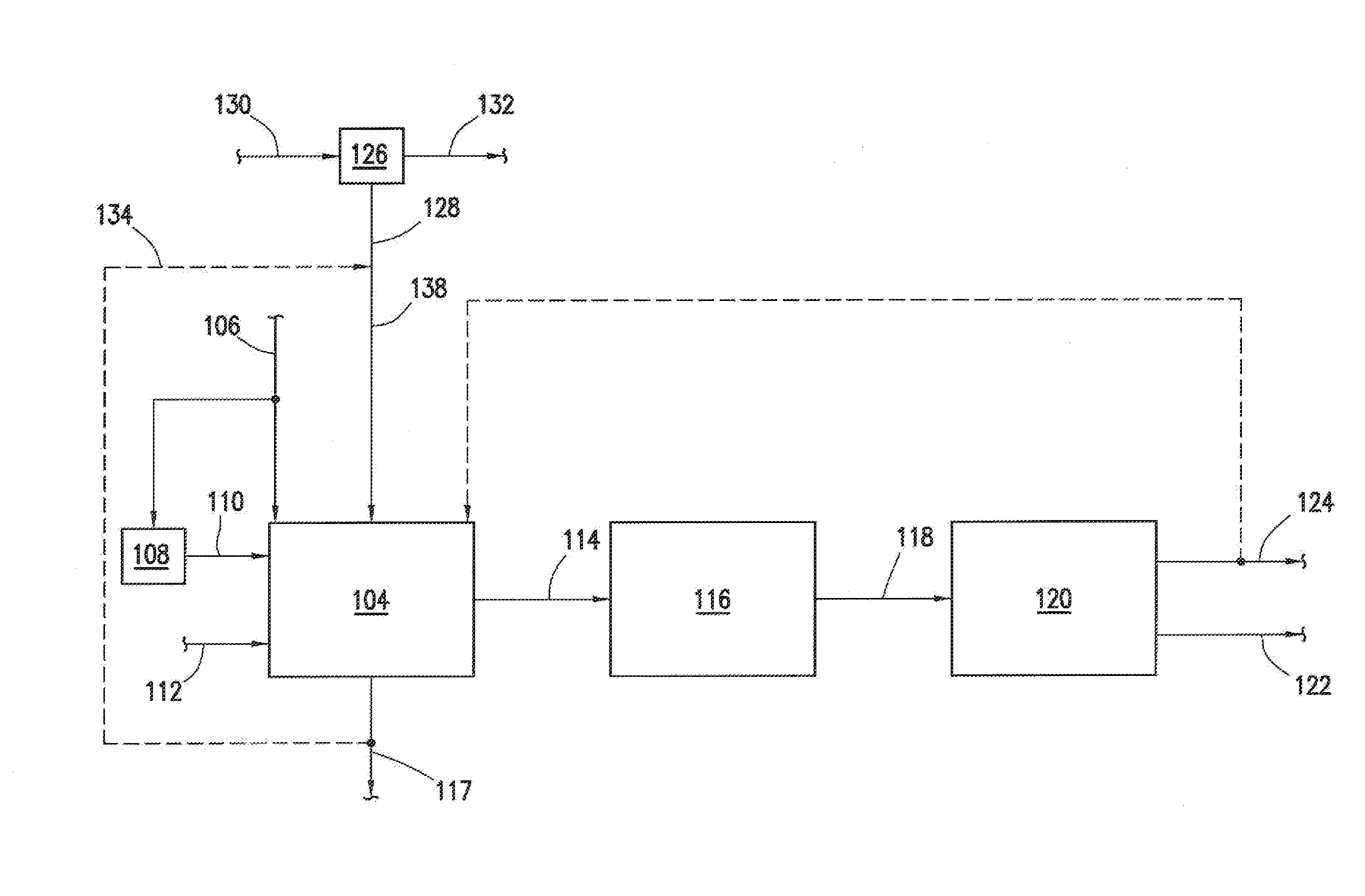
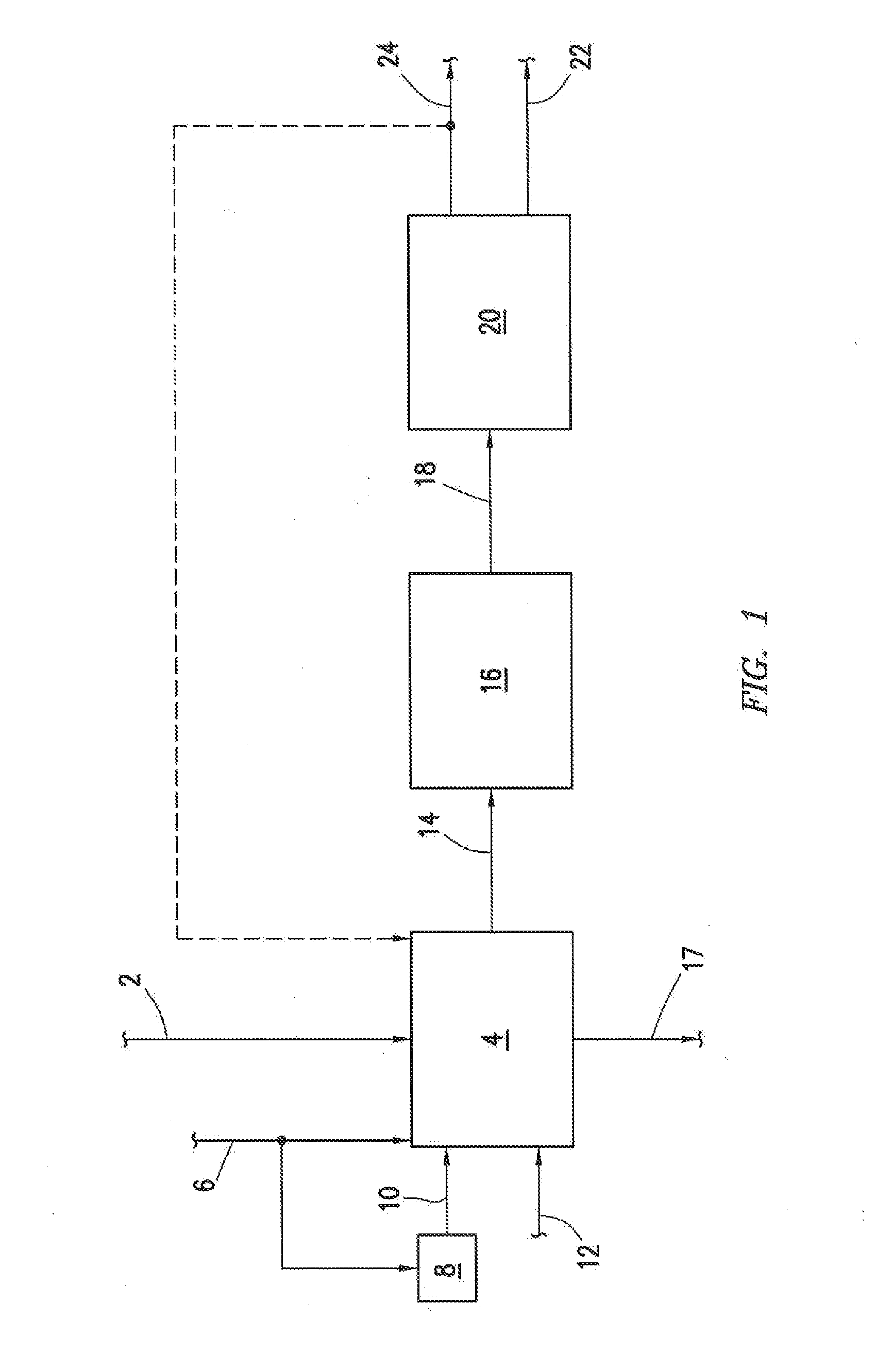
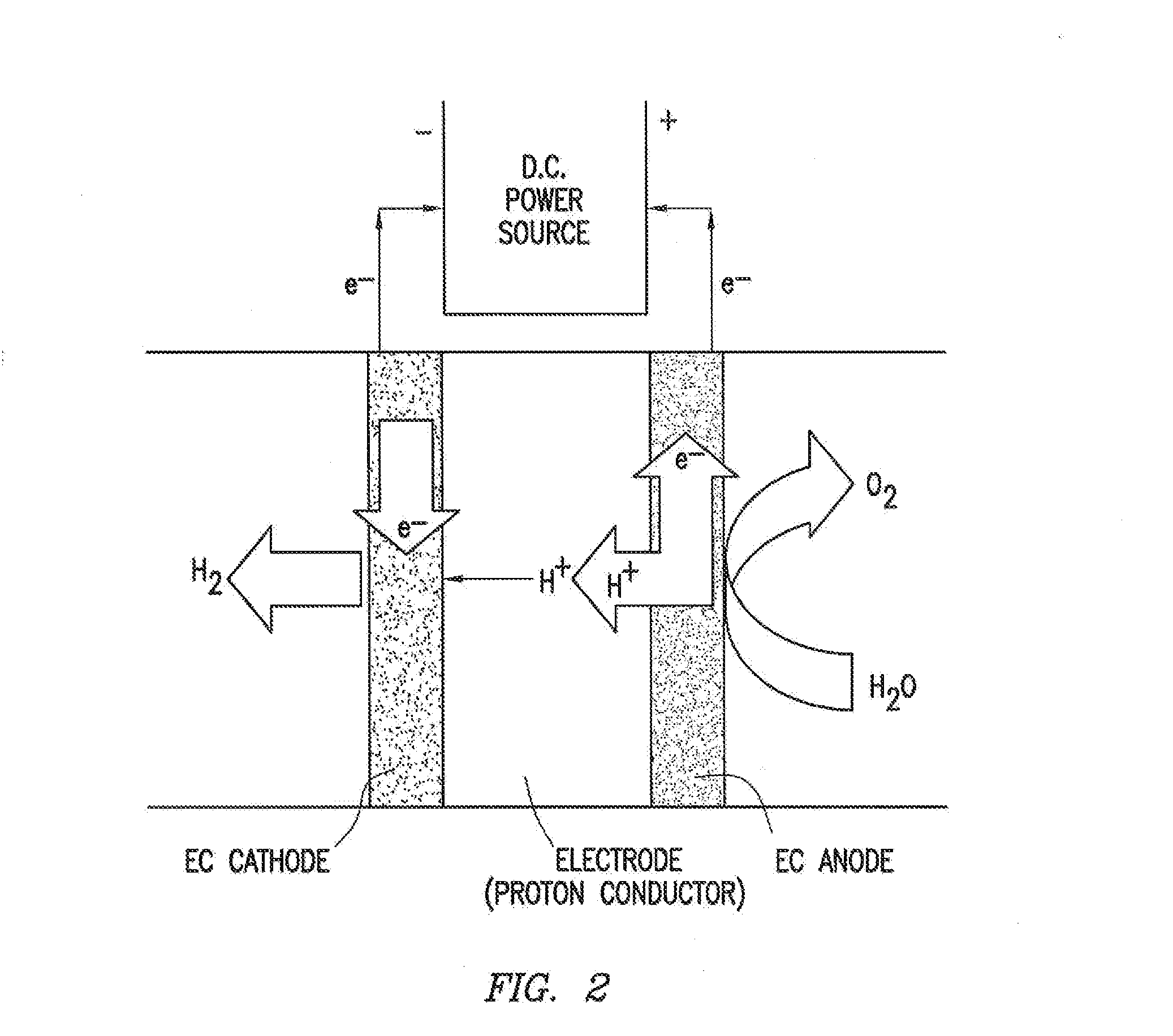
The patent describes a process for producing a feed from a solid oxide electrolysis cell using flue gas from a combustion process. The flue gas is directed to the anode side of the electrolysis cell to produce the feed, which contains oxygen and CO2. The feed is then mixed with a second portion of the flue gas and fuel, and combusted in the combustion process to produce the flue gas. The flue gas has a high content of CO2 and low content of N2. The technical effect of this process is the efficient production of a feed with a high content of CO2 and low content of N2, which can be utilized in various industrial applications such as chemical synthesis and power generation.

Problems solved by technology

On the other hand, combustion flue gas streams are mostly nitrogen, thus it is cost prohibitive to size an amine scrubber to process the entire streams.
The result is an upper limit to how much CO2 could be captured practically in a refinery.
One of the largest obstacles in operating an oxygen-fuel combustion process is obtaining oxygen.
The problems with air separation units is that they typically separate oxygen and nitrogen from air through a cryogenic separation process, which has large capital, operating costs and CO2 footprint associated.

Method used


Image

  • Process for enabling carbon-capture from existing combustion processes
  • Process for enabling carbon-capture from existing combustion processes
  • Process for enabling carbon-capture from existing combustion processes

Examples


Embodiment Construction

[0017]Turning now to the detailed description of the preferred arrangement or arrangements of the present invention, it should be understood that the inventive features and concepts may be manifested in other arrangements and that the scope of the invention is not limited to the embodiments described or illustrated. The scope of the invention is intended only to be limited by the scope of the claims that follow.

[0018]The following examples of certain embodiments of the invention are given. Each example is provided by way of explanation of the invention, one of many embodiments of the invention, and the following examples should not be read to limit, or define, the scope of the invention.

[0019]Any conventionally used and / or known combustion process can be used. Two known combustion processes are steam methane reformer (SMR) furnaces or fluidized catalytic cracker (FCC) regenerators.

[0020]One example where a combustion process is used is a SMR process. Generally, SMR processes can be ...


PUM

PropertyMeasurementUnit
Fractionaaaaaaaaaa
Pressureaaaaaaaaaa

Abstract

A process of producing a feed from a solid oxide electrolysis cell. A first portion of the flue gas produced from a combustion process is directed to the anode side of the solid oxide electrolysis cell. The feed and a second portion of the flue gas are then mixed to produce an enhanced feed. The enhanced feed is then mixed with fuel and combusted in the combustion process to produce flue gas. The flue gas comprises greater than 50 wt % CO2 and less than 1 wt % N2.

Description

CROSS-REFERENCE TO RELATED APPLICATIONS[0001]This application is a non-provisional application which claims the benefit of and priority to U.S. Provisional Application Ser. No. 61 / 701,792 filed Sep. 17, 2012, entitled “Process for Enabling Carbon-Capture from Existing Combustion Processes,” which is hereby incorporated by reference in its entirety.STATEMENT REGARDING FEDERALLY SPONSORED RESEARCH OR DEVELOPMENT[0002]None.FIELD OF THE INVENTION[0003]This invention relates to a process for enabling carbon-capture from existing combustion processes.BACKGROUND OF THE INVENTION[0004]Conventional combustion processes have associated CO2 emissions that have been identified as an area for potential reduction of greenhouse gas emissions within refineries.[0005]Technologies such as amine scrubbing can remove CO2 from process gas streams, such as the flue gas waste stream from combustion processes such as a steam methane reformer (SMR) furnace or a fluidized catalytic cracker (FCC) regenerator....

Claims


Application Information

Patent Timeline
IPC IPC(8): F23L7/00F23C9/00B01D53/76
CPCF23L7/007F23C9/00B01D53/76B01D53/047B01D2256/16B01D2257/504C01B3/38C01B3/384C01B2203/0233C01B2203/0283C01B2203/043C01B2203/1241C25B1/00C25B1/04C25B15/08F23J2215/40F23J2215/50F23L7/005Y02E20/32Y02E20/34Y02E60/36Y02P20/151
Inventor INGRAM, DAVID B.PAUL, UCHENNA P.
Owner PHILLIPS 66 CO
Why Eureka
Eureka Blog
Learn More