
System and method for user equipment centric unified system access in virtual radio access network

a unified system and radio access technology, applied in the direction of eavesdropping prevention circuits, wireless commuication services, assessing restrictions, etc., can solve the problems of poor link between the ue and the serving cell, the number of access sequences is limited per cell, and the connection setup is long and inefficien

Active Publication Date: 2014-03-13
HUAWEI TECH CO LTD
View PDF8 Cites 44 Cited by
  • Summary
  • Abstract
  • Description
  • Claims
  • Application Information

AI Technical Summary

Benefits of technology

The present invention is a new technology that is described in detail. Various changes, modifications, and alterations can be made to this technology without changing its main purpose and scope. The technology has been designed to explain its principles and practical applications in a way that allows others to use it with various modifications as needed.

Problems solved by technology

However, there are a limited number of access sequences per cell.
Reperforming the initial entry setup makes the connection setup very long and inefficient.
Unfortunately, because the handover process occurs on one or more cell boundaries, the signal strength of the airlink is limited which possibly results in a poor link between the UE and the serving cell.
The inefficiency is further exposed when the UE ping-pongs or moves back and forth between the two cells, requiring increased signaling overhead for the same UE accessing the cellular network.
As a result, the current UE / cell based network access scheme may not be compatible with transmit point virtualization.
The current UE / cell association access scheme is inefficient as it a UE may have to perform multiple, costly initial entry setup processes within a cell boundary or when performing a handover process.
In addition, the current access scheme may be unsuitable for high density UE terminals and devices (e.g., smart meters, etc.).
Furthermore, the current access scheme may not be applicable to future wireless networks, in which two or more transmit / receive points may serve one UE to enhance communication link quality, or where the number of transmit / receive points serving one (e.g., mobile) UE can vary with these network configurations being transparent to the UE.

Method used


Image

  • System and method for user equipment centric unified system access in virtual radio access network
  • System and method for user equipment centric unified system access in virtual radio access network
  • System and method for user equipment centric unified system access in virtual radio access network

Examples


Embodiment Construction

[0027]Reference will now be made in detail to the various embodiments of the present disclosure, examples of which are illustrated in the accompanying drawings. While described in conjunction with these embodiments, it will be understood that they are not intended to limit the disclosure to these embodiments. On the contrary, the disclosure is intended to cover alternatives, modifications and equivalents, which may be included within the spirit and scope of the disclosure as defined by the appended claims. Furthermore, in the following detailed description of the present disclosure, numerous specific details are set forth in order to provide a thorough understanding of the present disclosure. However, it will be understood that the present disclosure may be practiced without these specific details. In other instances, well-known methods, procedures, components, and circuits have not been described in detail so as not to unnecessarily obscure aspects of the present disclosure.

[0028]A...


PUM


Abstract

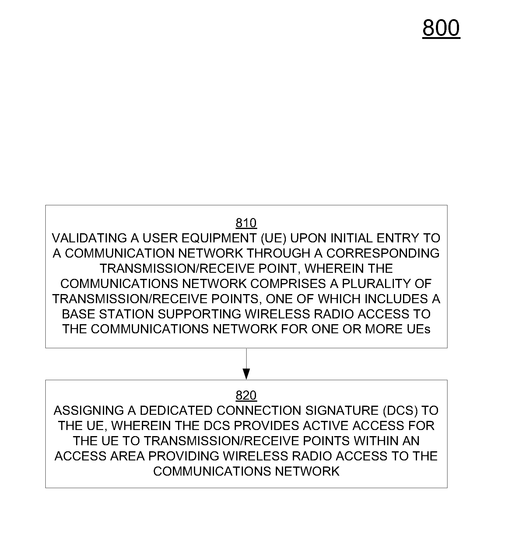
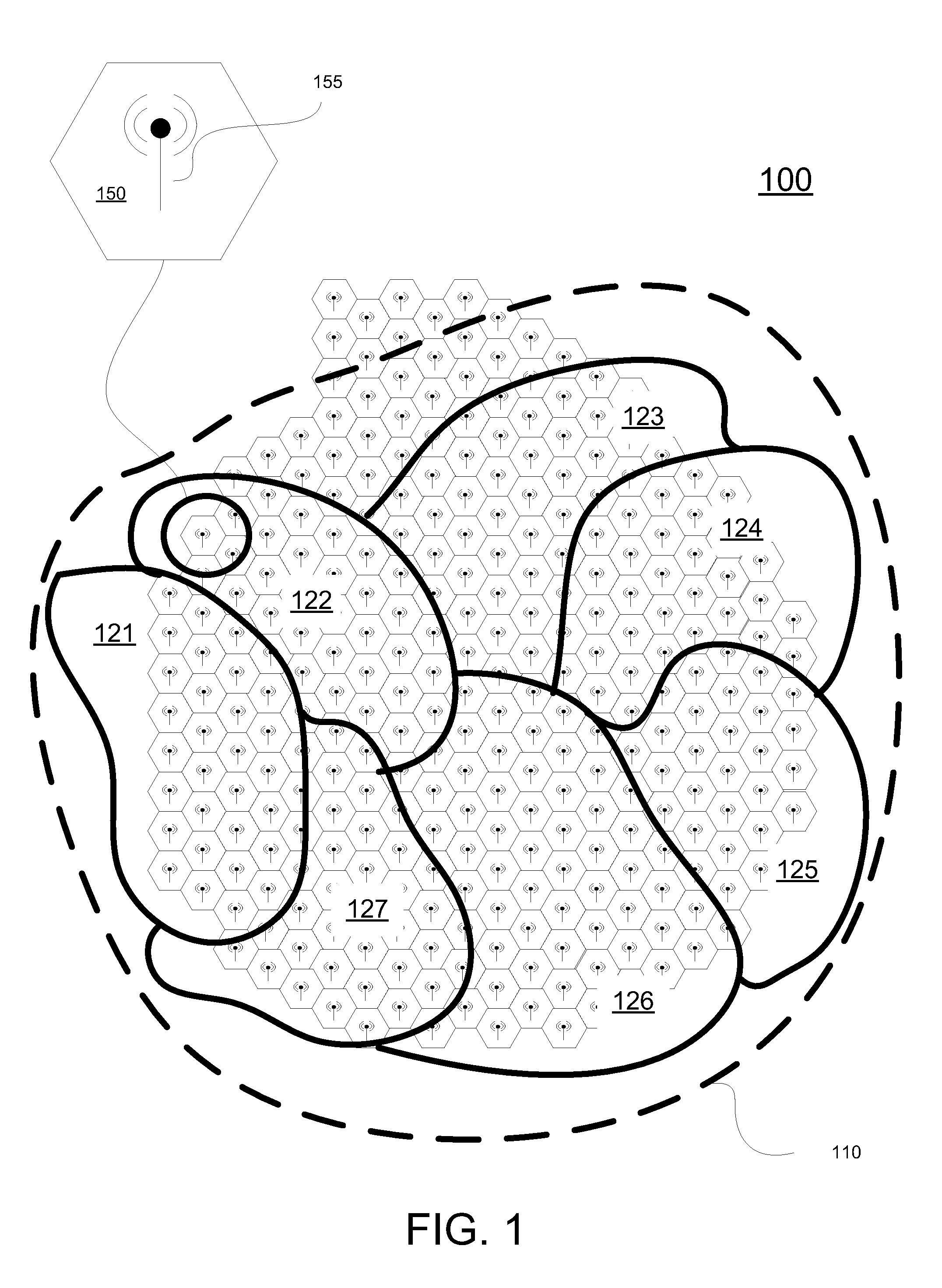
A network for facilitating wireless radio communication. The network includes a first access area, wherein the access area includes one or more transmission / receive points. At least one transmission / receive point includes a base station that supports wireless communication between a network and user equipment (UE), such as, a mobile device. The network includes a dedicated connection signature (DCS) that is assigned to a UE. The DCS provides for and is used by the UE to maintain active, unified access to the wireless network. More particularly, the DCS provides for active, contention free, and fast access for the UE to the network through transmission / receive points within the first access area, which is of significance to present and future UE centric virtual radio access networks having high densities of mobile and non-mobile users and with high populations of different types of traffic patterns and applications.

Description

BACKGROUND[0001]A cellular network provides wireless access for user equipment (UE) (e.g., mobile phones, computers, transceivers, etc.) for purposes of communication. The network includes multiple cells, each supported by a base station that is used for transmitting and receiving communication signals. Collectively, the cells provide wireless, radio coverage over a large geographic area. In this manner, UEs are able to communicate with each other throughout the cellular network. Additionally, the cellular network is able to connect with other networks (public switched telephone network, other cellular networks, internet based networks, etc.) to facilitate communication between devices connecting to any of the available networks.[0002]In order to transmit information (e.g., voice, data, etc.) over the cellular network, a UE must first perform a network connection or initial entry setup with a serving cell in order to identify and validate itself to the network. This occurs under var...

Claims


Application Information

Patent Timeline
Patent Type & Authority Applications(United States)
IPC IPC(8): H04W4/00H04W12/06H04W40/00
CPCH04W48/20H04L5/0016H04W12/06H04W74/00H04W76/11H04W12/75H04W12/79H04W72/51H04W36/0027
Inventor ZHANG, LIQINGMA, JIANGLEIAU, KELVINYI, ZHIHANG
Owner HUAWEI TECH CO LTD
Learn More