
High pressure intensifiers

a technology of intensifier and high pressure, which is applied in the direction of piston pumps, servomotors, borehole/well accessories, etc., can solve the problems of high cost of an additional high pressure line in an umbilical from a surface platform to a well, leakage of devices, and high cost of current subsea intensifiers. achieve the effect of greater surface area

Active Publication Date: 2014-03-13
BAKER HUGHES ENERGY TECH UK LTD
View PDF3 Cites 11 Cited by
  • Summary
  • Abstract
  • Description
  • Claims
  • Application Information

AI Technical Summary

Benefits of technology

The invention is a pressure intensifier that uses commonly available pilot valves to operate a pair of pistons in a way that eliminates expensive and complex designs. The pressure intensifier does not suffer from hydraulic fluid leakage, which is a common issue in current designs.

Problems solved by technology

The cost of an additional high pressure line in an umbilical from a surface platform to a well is very expensive, so subsea pressure intensification, local to the well tree, is sometimes used.
Current subsea intensifiers are highly engineered, and can be expensive and unreliable.
In this condition, these devices leak from a low pressure supply, to a return.
This can compromise the function of the field and the change-over valve concerned can only be unstuck by actuating the SSSV to ‘consume’ some high pressure fluid.
The SSSV is functionally critical to the oil well and can not easily be replaced if it wears out.

Method used


Image

  • High pressure intensifiers
  • High pressure intensifiers
  • High pressure intensifiers

Examples


Embodiment Construction

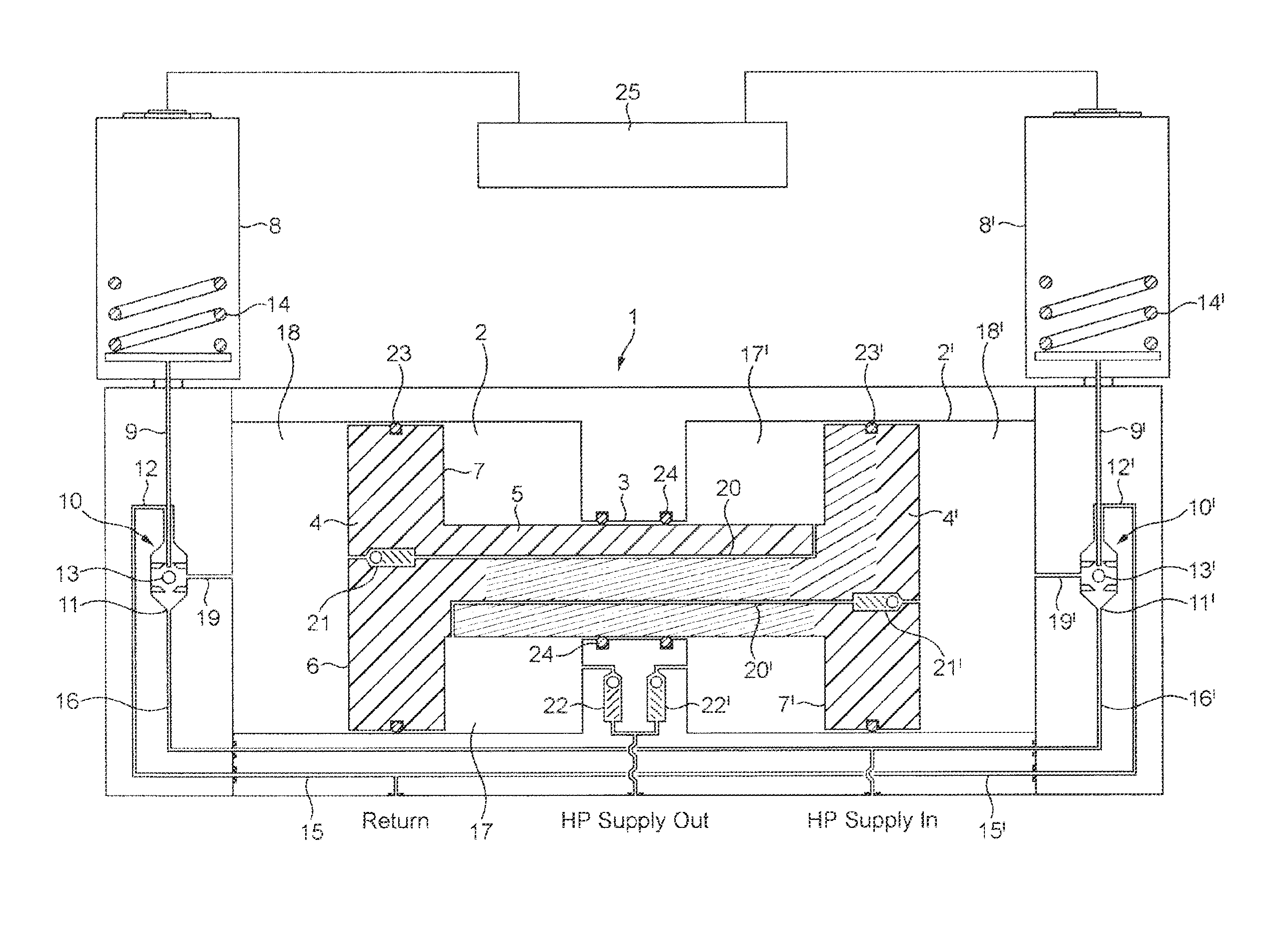
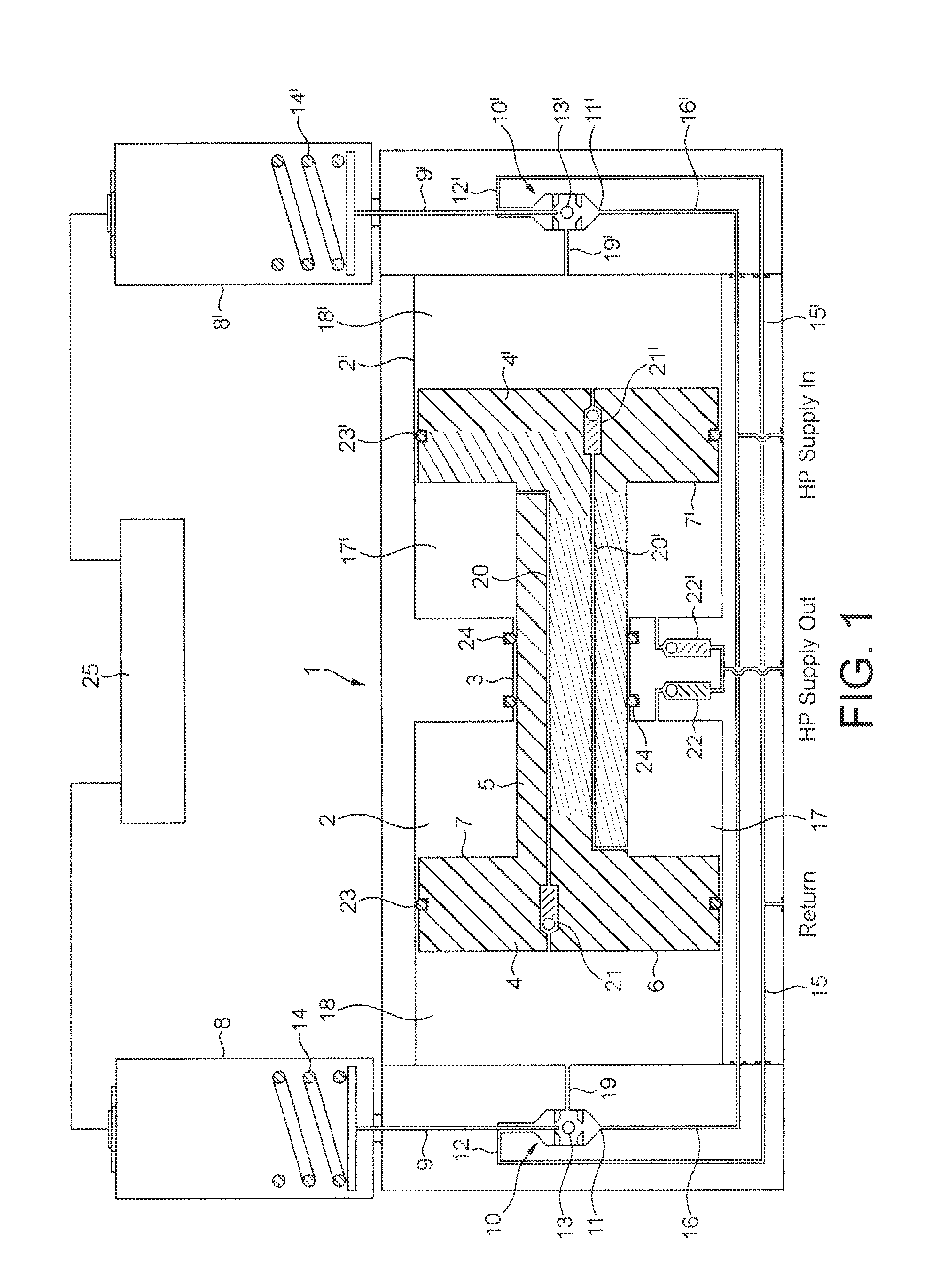
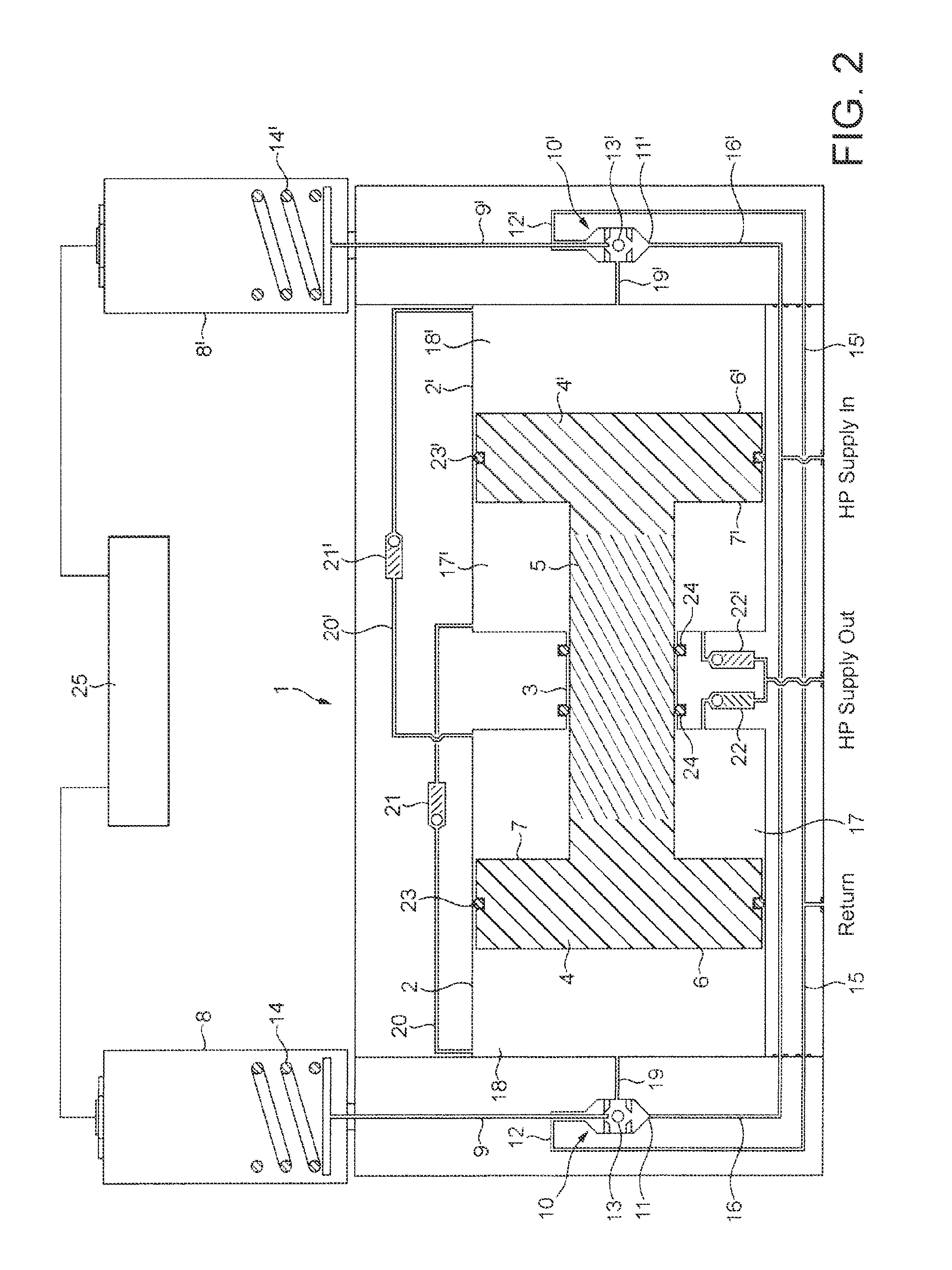
[0024]Referring to FIG. 1, a double-acting hydraulic intensifier 1 comprises first and second cylinders 2 and 2′ joined by a narrower cylinder section 3. Reciprocally slidable in cylinder 2 is a piston 4 and reciprocally slidable in cylinder 2′ is a piston 4′, pistons 4 and 4′ being joined by a cylindrical member 5 extending through and slidable in cylinder section 3. By virtue of member 5, piston 4 has a first face 6, on the left-hand side in the figure, which has a greater surface area than its second, opposite face 7 and piston 4′ has a first face 6′, on the right-hand side in the figure, which has a greater surface area than its second, opposite face 7′.

[0025]Each side of the intensifier comprises a solenoid operated pilot valve. More particularly, on each side there is: a solenoid 8 or 8′ which operates a push rod 9 or 9′; and a hydraulic pilot valve 10 or 10′ that has two ports 11 and 12 or 11′ and 12′ that can be closed by a small ball bearing 13 or 13′ that is loose between ...


PUM


Abstract

A hydraulic intensifier comprising a reciprocating differential piston arrangement and a controller configured to control the supply of low pressure hydraulic fluid to the intensifier is provided. The controller comprises at least one solenoid operated pilot valve and electronic operator configured to operate the pilot valve.

Description

CROSS-REFERENCE TO RELATED APPLICATIONS[0001]This is a national stage application under 35 U.S.C. §371(c) prior-filed, co-pending PCT patent application serial number PCT / EP11 / 069172, filed on Oct. 31, 2011, which claims priority to EP Application Serial No. 10189641.3, filed Nov. 2, 2010, the disclosure of which is hereby incorporated in their entirety by reference herein.BACKGROUND OF THE INVENTION[0002]The present invention relates to high pressure intensifiers.[0003]Within the subsea oil industry, subsea trees require few high pressure valve functions. For most wells, often only one high pressure valve, typically the subsea safety valve (SSSV), is required on each well head tree. This valve requires a source of high pressure hydraulic fluid at the seabed. The cost of an additional high pressure line in an umbilical from a surface platform to a well is very expensive, so subsea pressure intensification, local to the well tree, is sometimes used. This is particularly cost-effectiv...

Claims


Application Information

Patent Timeline
IPC IPC(8): F15B3/00
CPCF15B3/00E21B33/0355F04B9/115F04B49/06F04B9/1095F15B9/03
Inventor ROBERTS, TIMOTHY JAMES
Owner BAKER HUGHES ENERGY TECH UK LTD
Learn More