
Subpixel Resolution by Interpolation of Crosstalk from Adjacent Pixels

a crosstalk and subpixel technology, applied in the field of camera focal plane arrays, can solve the problems of sensor speed, advanced weapons pose similar challenges, and system not providing desired and required capabilities to address new threats

Inactive Publication Date: 2014-03-06
SCOTT BASIL HENRY +2
View PDF1 Cites 13 Cited by
  • Summary
  • Abstract
  • Description
  • Claims
  • Application Information

AI Technical Summary

Benefits of technology

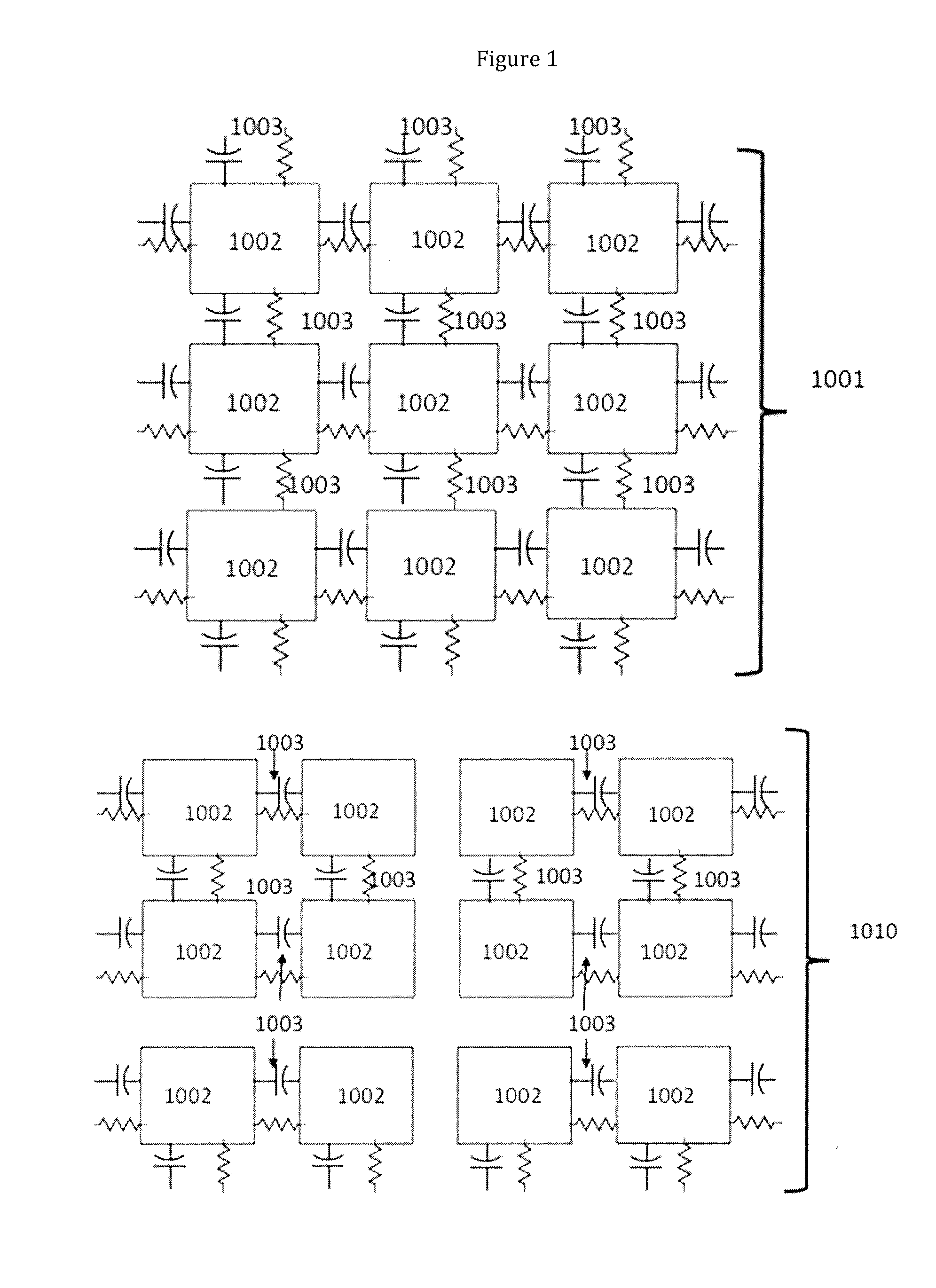
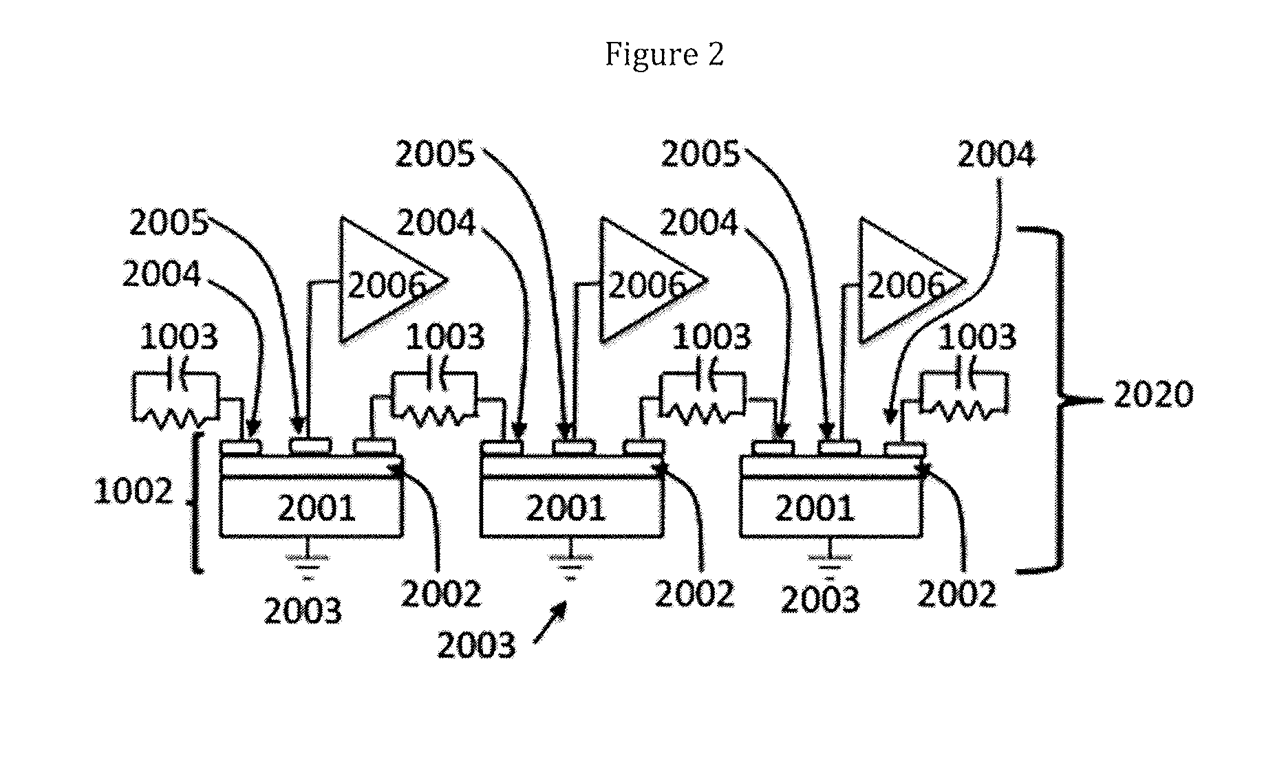
The patent describes a process for achieving subpixel resolution of a light spot on a focal plane array by interconnecting pixels with interconnections that have signal changing properties. The process involves measuring crosstalk current flows caused by the light spot and calculating the signal metrics of the current flows using a method selected from a look up table or position calculation equations. The resolution of the light spot can be determined by relating the signal metrics to a position on the array. The invention also includes a pixel array with interconnected pixels that have signal changing properties, which allows for subpixel sensing. The technical effects of the invention include improved image quality and reduced noise amplification.

Problems solved by technology

In many cases, these systems do not provide desired and required capabilities to address new threats.
Both the unsophisticated and the advanced weapons pose similar challenges to detector technology.
The first issue is sensor speed.
A second issue is precision threat location.
Unfortunately, increasing the precision of threat location is a competing requirement with high-speed operation.
Increasing both the total frame rate and the total number of pixels in each frame (pixel count) can result in an unacceptably large increase in total input / output (I / O) signals or data.
Furthermore, some technology components to handle this large data rate might not be available, or would be prohibitive in cost, size, weight, or power.

Method used


Image

  • Subpixel Resolution by Interpolation of Crosstalk from Adjacent Pixels
  • Subpixel Resolution by Interpolation of Crosstalk from Adjacent Pixels
  • Subpixel Resolution by Interpolation of Crosstalk from Adjacent Pixels

Examples


Embodiment Construction

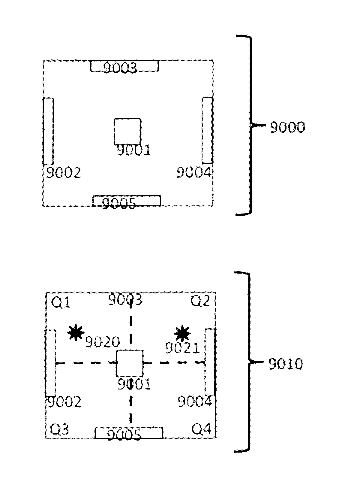
[0036]The present invention is an interconnected pixel array with subpixel resolution sensing, that is, resolution more precise than a single pixel. It is a detector geometry that provides a subpixel positional location capability (subpixel sensing) for an imaged point source. The present invention supports large or small pixel sizes and a high or low array element count. It can be implemented in any p-on-n or n-on-p diode detector, or any other pixel based detector that experiences crosstalk from adjacent pixels.

[0037]Crosstalk is any phenomenon by which a primary signal transmitted on one circuit or channel of a transmission system creates another signal (a crosstalk signal) in another circuit or channel. Crosstalk typically degrades performance and is usually highly undesirable. Crosstalk is usually caused by unwanted capacitive, inductive, conductive or other coupling from one circuit, part of a circuit, or channel, to another. The presently preferred embodiment of the invention...


PUM


Abstract

A pixel interconnect circuit that can be added to a focal plane array, which enables subpixel location capability (subpixel sensing) for an imaged point source and facilitates very high frame rate operation. The pixel interconnect is typically added as a circuit component within the readout integrated circuit. The interconnect function can be turned on or off, allowing for flexible operation. It allows for the use of very low pixel count arrays, such as 128×128 pixels, to achieve the positional accuracy of multi-megapixel arrays. In turn, these small arrays can be clocked at very fast frame rates for enhanced threat and fast event detection. Existing systems can be upgraded by adding the pixel interconnect, which will greatly improve tracking and position accuracy without increasing data processing requirements. By modifying the focal plane while leaving other components unchanged, the pixel interconnect provides an economical upgrade for older threat warning and tactical sensor systems.

Description

[0001]This application claims the priority of U.S. provisional patent application no. 61 / 531,542 filed Sep. 6, 2011.TECHNICAL FIELD[0002]The present invention generally relates to camera focal plane arrays. More specifically, the invention relates to a process and device for optimizing camera focal plane arrays used in threat detection systems, tactical warning systems, and other special security systems. The camera focal plane array of the present invention can be fabricated from multiple materials and can operate in the ultraviolet (UV), visible, or infrared (IR) spectral bands.BACKGROUND ART[0003]Current military threat detection optical sensors are optimized to work against “traditional” threats such as heat-seeking surface-to-air missiles targeting aircraft. In many cases, these systems do not provide desired and required capabilities to address new threats. These new threats include unsophisticated weapons, such as those used by irregular militia in Afghanistan, as well as adv...

Claims


Application Information

Patent Timeline
IPC IPC(8): H04N5/365
CPCH04N5/365H01L27/14609H04N23/815H04N25/62H04N25/67
Inventor SCOTT, BASIL HENRY
Owner SCOTT BASIL HENRY
Learn More