
Optical sorting machine

a sorting machine and optical technology, applied in the direction of sorting, etc., can solve the problems of increasing the size and cost of the machine, and the inability of the secondary sorting unit to efficiently collect non-defective products, so as to improve the collection rate of non-defective products, increase the size of the machine, and reduce the amount

Active Publication Date: 2014-03-06
SATAKE CORP
View PDF2 Cites 12 Cited by
  • Summary
  • Abstract
  • Description
  • Claims
  • Application Information

AI Technical Summary

Benefits of technology

The present invention provides an optical sorting machine that can efficiently collect non-defective products from a mixed stream of non-defective and defective products. The machine has a discharge hopper with multiple discharge passages, allowing interlevel products to be re-sorted in the optical sorting unit. The machine also includes conveyance means and angle adjustment plates to control the amount of objects entering each discharge passage, adjusting the purity and mix rate of products. Overall, the invention improves the collection rate of non-defective products without increasing the size of the machine.

Problems solved by technology

The optical sorting machine described in Patent Literature 1, however, has a problem that the machine is increased in size and cost since it is necessary to provide two sets of sorting units.
The optical sorting machine described in Patent Literature 1 also has a problem that, while many non-defective products caught in the air for removing defective products are mixed into the defective products conveyed to the secondary tank 121b, the secondary sorting unit cannot efficiently collect the non-defective products because its processing capacity is limited.

Method used


Image

  • Optical sorting machine
  • Optical sorting machine
  • Optical sorting machine

Examples


Embodiment Construction

[0033]Embodiments of the present invention will be drawings.

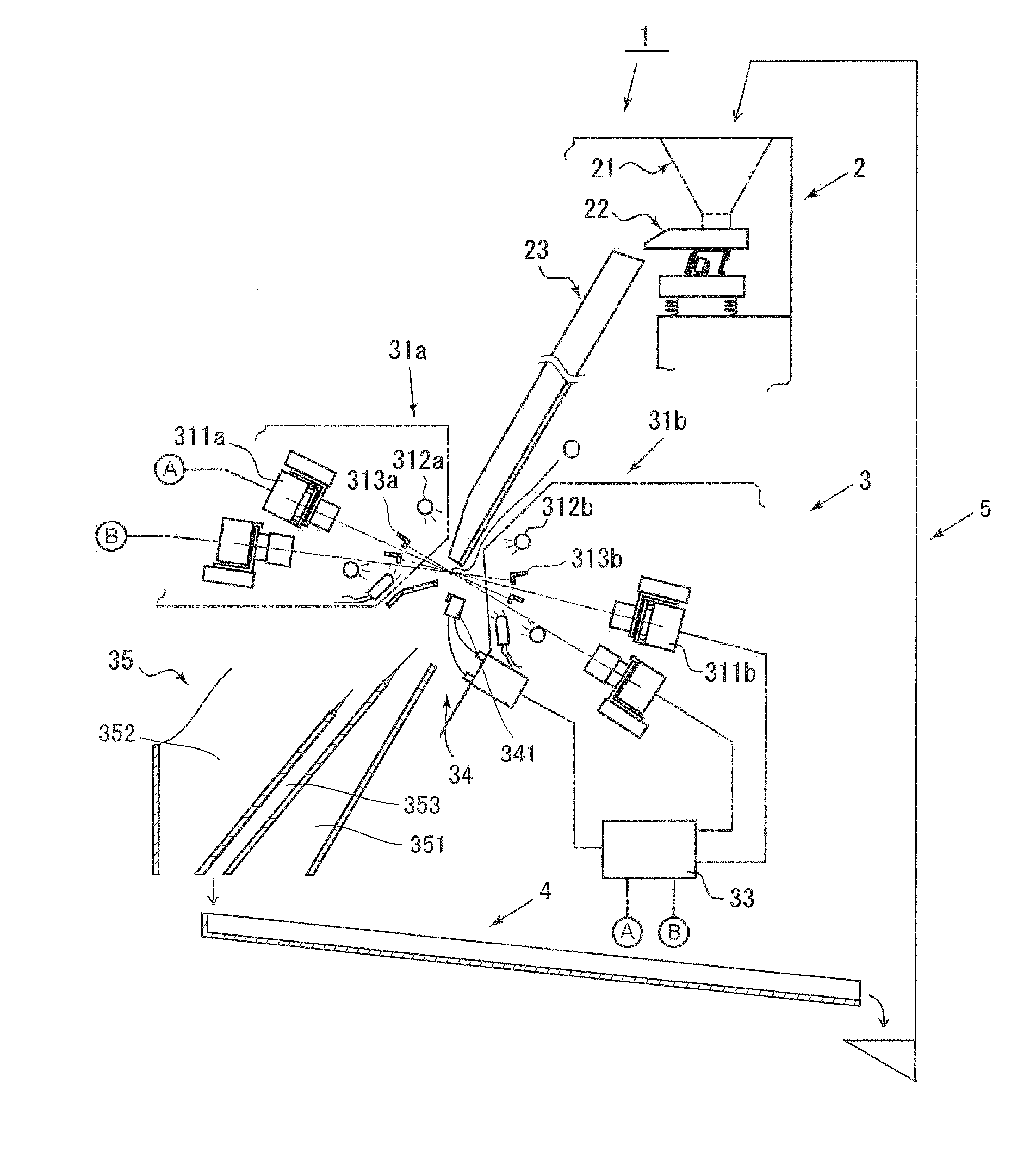
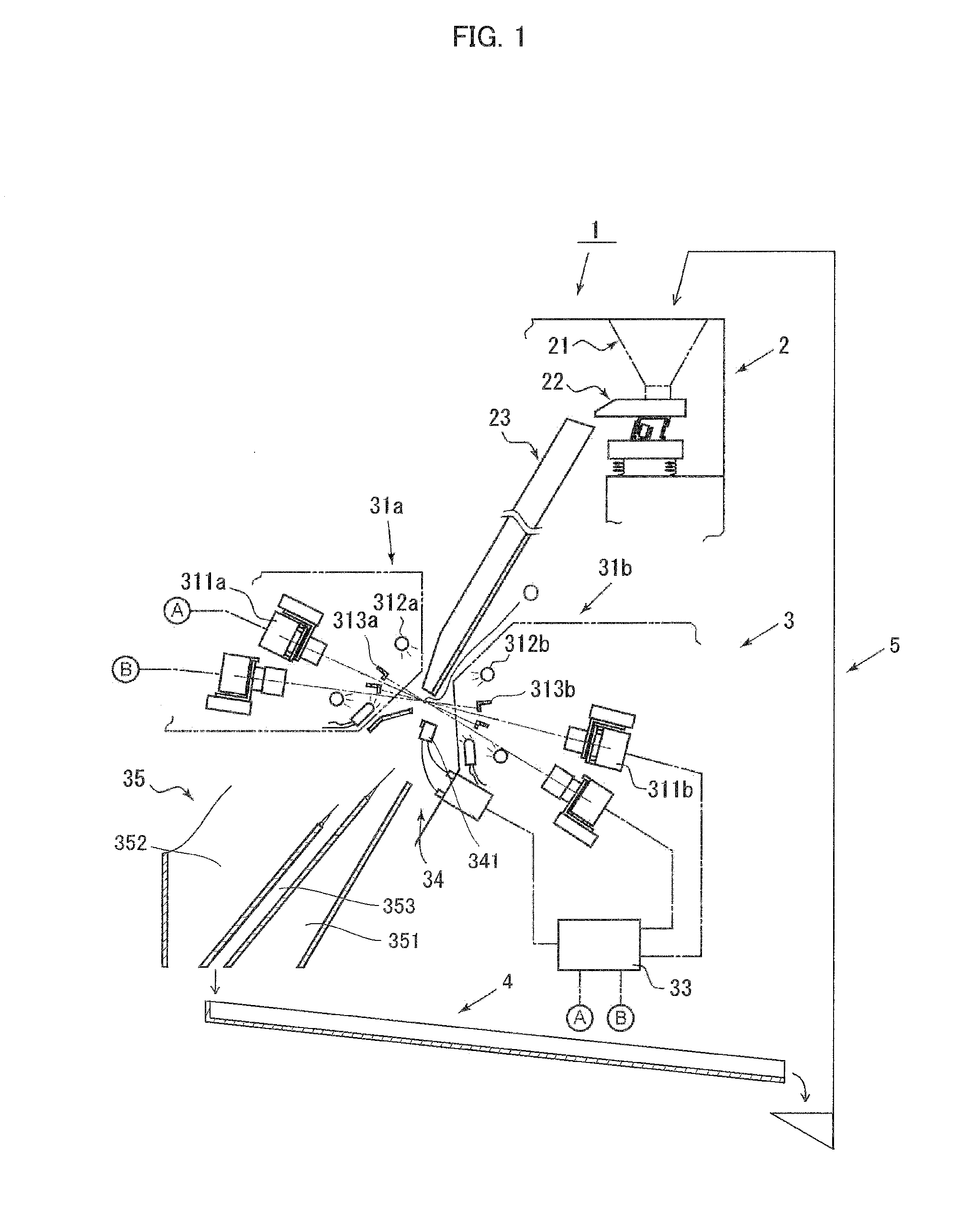
[0034]FIG. 1 shows a side sectional view of the simplified internal structure of an optical sorting machine according to an embodiment of the present invention.

[0035]The optical sorting machine according to the present embodiment includes a granular object feed unit 2, an optical sorting unit 3, a gutter-like passage 4, and an elevator 5.

[0036]In the optical sorting machine according to the present embodiment, the granular object feed unit 2 includes a raw material tank 21, a vibrating feeder 22 that feeds granular objects stored in the raw material tank 21, and an inclined chute 23 with a predetermined width that causes the granular objects fed from the vibrating feeder 22 to flow down.

[0037]Here, the vibrating feeder 22 is placed on a vibration generating device having a vibrator or the like, and can control the feed of the granular objects to the inclined chute 23 by adjusting a frequency or a vibration in the vibration ...


PUM


Abstract

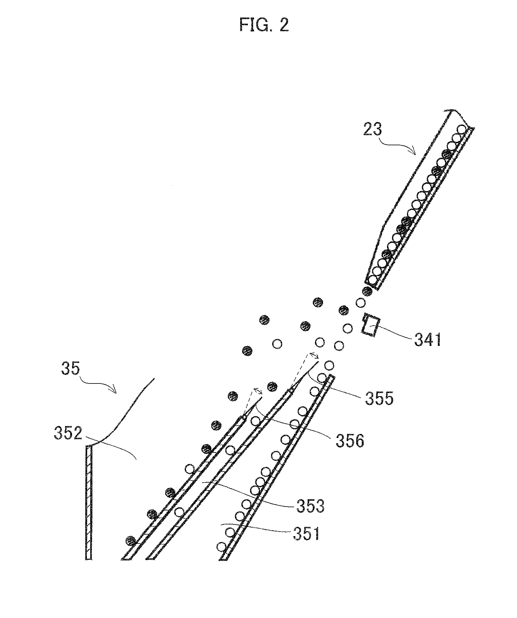
The present invention intends to provide an optical sorting machine which can improve the collection rate of non-defective products without increasing the size of the machine. The optical sorting machine of the present invention includes a granular object feed unit including storage means that stores an object to be sorted, and transfer means that transfers the object to be sorted from the storage means; an optical sorting unit including optical detection means that detects an object to be sorted falling along a predetermined trajectory from an end portion of the transfer means, determination means that determines a type of the object to be sorted based on a detection signal from the optical detection means, an ejector that removes an object to be sorted determined as a specific type from the predetermined falling trajectory based on a determination result by the determination means, and a discharge hopper having a first discharge passage provided at a falling position of the object to be sorted falling along the predetermined trajectory, a second discharge passage provided at a falling position of the object to be sorted removed from the predetermined falling trajectory, and a third discharge passage formed between the first discharge passage and the second discharge passage; and conveyance means that conveys an object to be sorted discharged from the third discharge passage of the discharge hopper in the optical sorting unit to the storage means of the granular object feed unit.

Description

TECHNICAL FIELD[0001]The present invention relates to an optical sorting machine which sorts granular objects such as grains and resin pellets based on color or the like.BACKGROUND ART[0002]There has been conventionally known an optical sorting machine which sorts a raw material of grains such as rice, wheat, pulses and nuts, resin pieces such as pellets and beads, fine articles such as medicines, ores and whitebait, or other granular objects into non-defective products and defective products, and removes foreign objects or the like mixed into the raw material.[0003]This type of optical sorting machine illuminates granular objects falling along a predetermined trajectory from an end portion of a transfer passage, detects defective products or foreign objects included in the raw material upon receiving reflected light or the like from the granular objects, and removes the detected defective products or foreign objects, thereby sorting the granular objects.[0004]While the optical sort...

Claims


Application Information

Patent Timeline
IPC IPC(8): B07C5/342
CPCB07C5/342B07C5/3425B07C5/368B07C2501/0018B07C5/366
Inventor ITO, TAKAFUMIHARA, MASAZUMIMIYAMOTO, TOMOYUKI
Owner SATAKE CORP
Learn More