
Method for preparing a pattern to be printed on a plate or mask by electron beam lithography, corresponding printed circuit design system and computer program

a technology of electron beam lithography and printed circuit, applied in the field of lithography, can solve the problems of not being able to print certain complex geometric shapes, reducing accordingly the degree of freedom, and not being able to expose small shapes, so as to reduce the number of successive exposures and the total exposure time

Active Publication Date: 2014-02-27
COMMISSARIAT A LENERGIE ATOMIQUE ET AUX ENERGIES ALTERNATIVES +1
View PDF2 Cites 5 Cited by
  • Summary
  • Abstract
  • Description
  • Claims
  • Application Information

AI Technical Summary

Benefits of technology

The invention relates to a method for preparing a pattern to be printed using an electron beam. The method includes grouping together geometric shapes that have identical doses, in order to reduce the number of exposures required. This reduces the overall exposure time and improves the printing process.

Problems solved by technology

However, the reliability of current equipment does not make it possible to expose small shapes, in particular shapes with dimensions of less than 10 nm.
This reduces accordingly the degrees of freedom and does not necessarily make it possible to print certain complex geometric shapes.
Furthermore, this makes the determination of doses appreciably more complex, in particular since local overintensities in the intersections of shapes cannot be avoided.

Method used


Image

  • Method for preparing a pattern to be printed on a plate or mask by electron beam lithography, corresponding printed circuit design system and computer program
  • Method for preparing a pattern to be printed on a plate or mask by electron beam lithography, corresponding printed circuit design system and computer program
  • Method for preparing a pattern to be printed on a plate or mask by electron beam lithography, corresponding printed circuit design system and computer program

Examples


Embodiment Construction

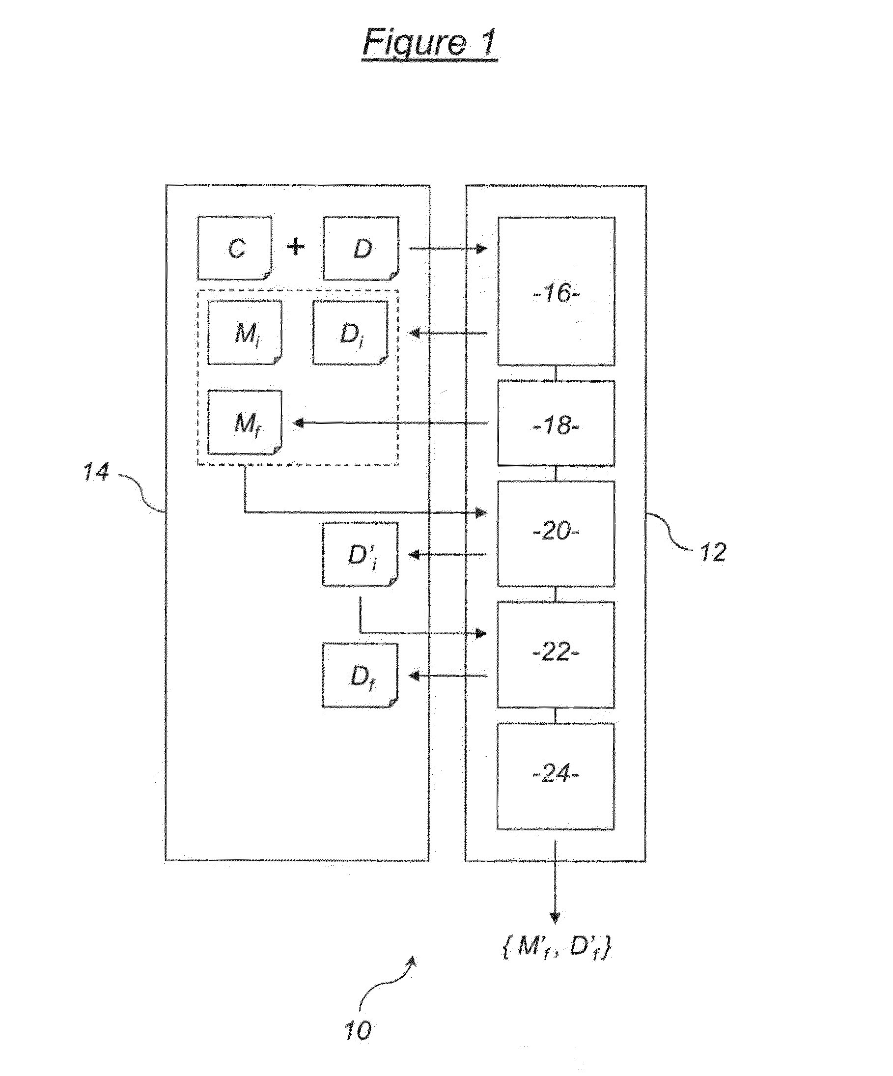
[0033]The printed circuit design system 10 shown schematically in FIG. 1 comprises a processing module 12 associated in a conventional fashion with a memory 14 (for example a RAM memory). It may for example be used in a data processing device such as a conventional computer comprising a processor associated with one or more memories for storing data files and computer programs. The processing module 12 can then itself be considered to be a form of processor associated with a memory for storing instructions that it executes in the form of computer programs.

[0034]The processing module 12 as illustrated in FIG. 1 thus functionally comprises five computer programs 16, 18, 20, 22 and 24.

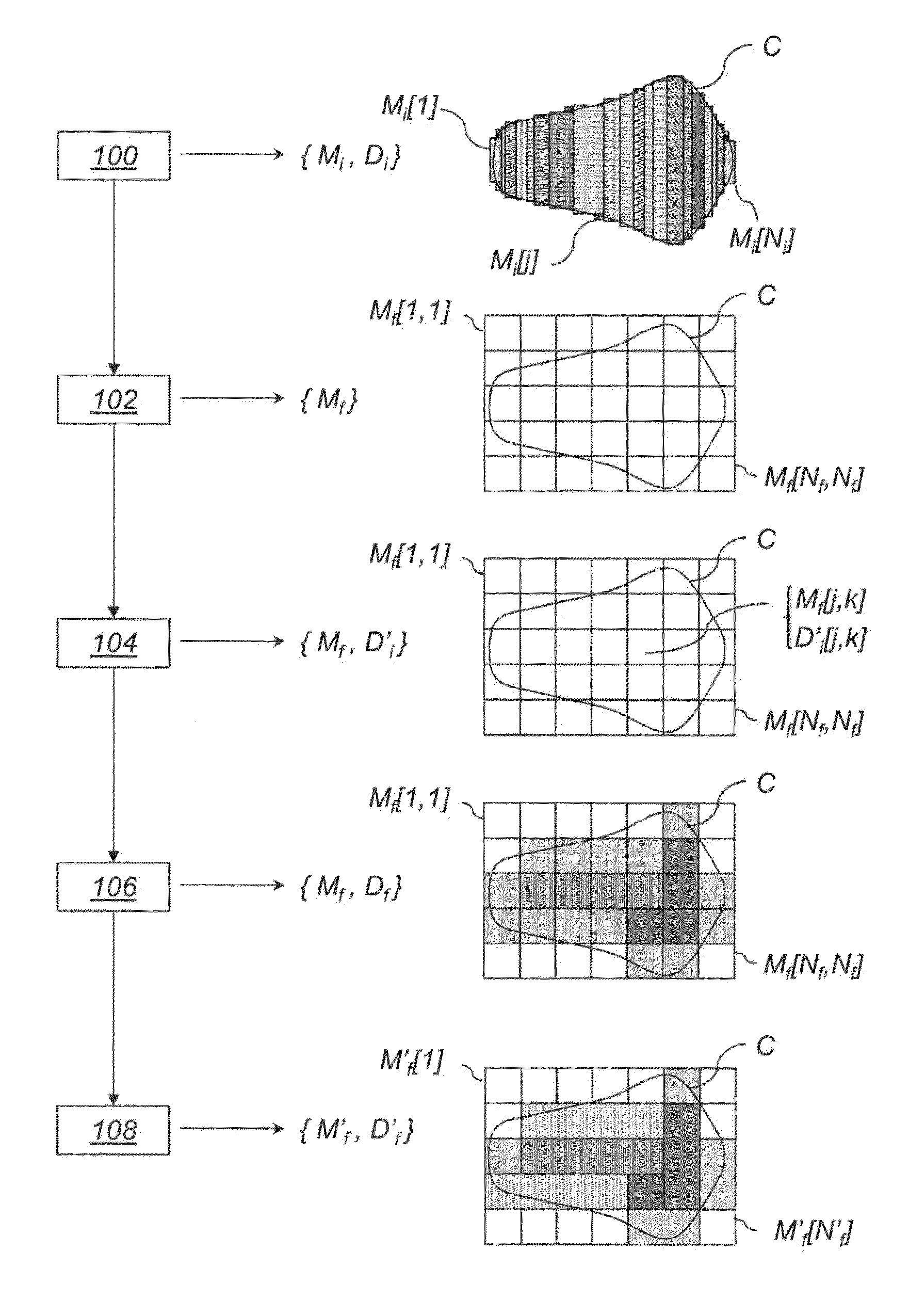
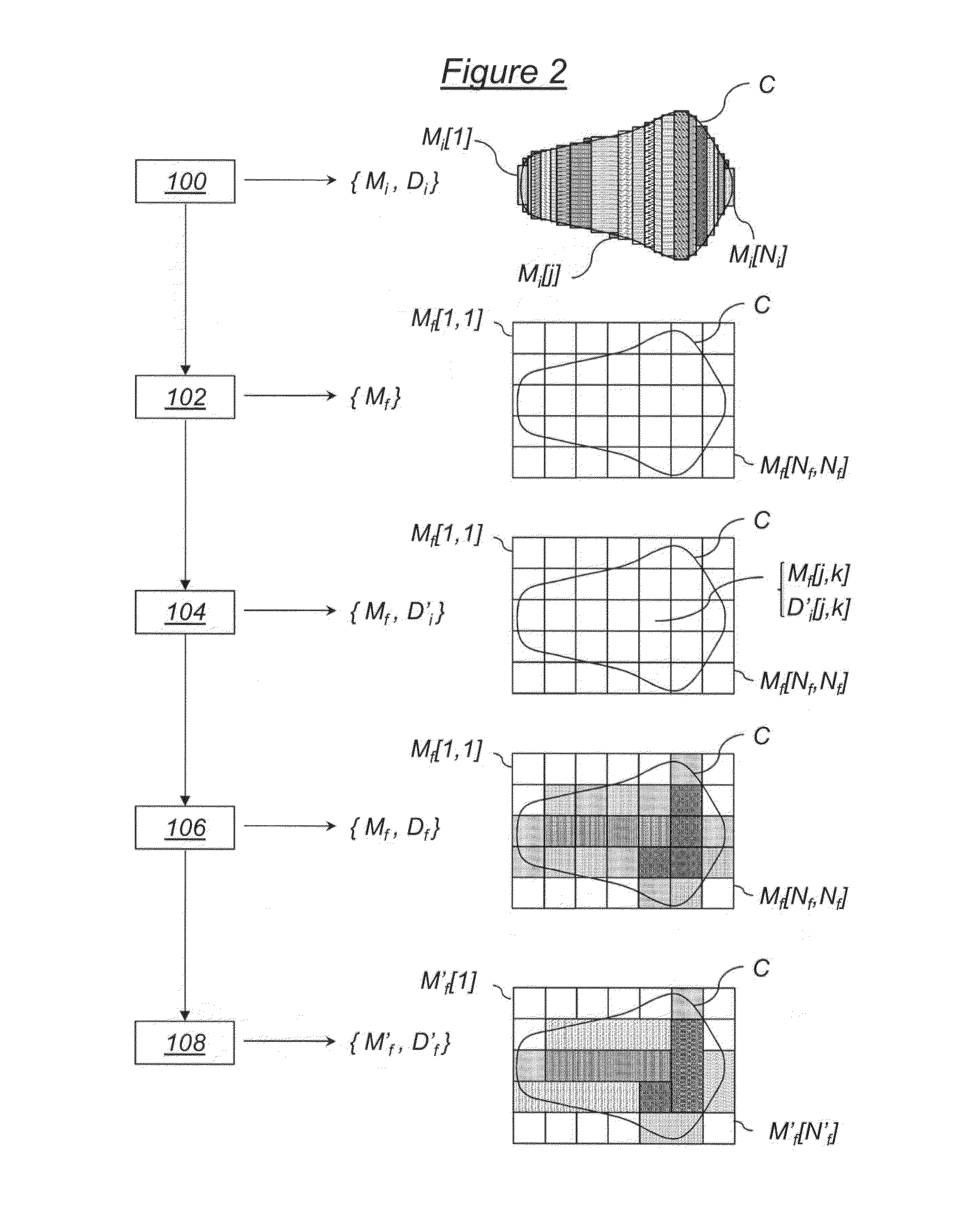
[0035]The first computer program 16 is a program for prior modelling of a given pattern the contour parameters of which are for example stored in memory 14. From the contour C of the pattern to be printed and optionally a table D of discrete dose values including several predetermined non-zero dose values...


PUM


Abstract

A method for preparing a pattern to be printed on a plate or mask by electron beam lithography comprising the following steps: modelling of the pattern by breaking down this pattern into a set of elementary geometric shapes intended to be printed individually in order to reproduce said pattern and, for each elementary geometric shape of the model; determination of an electrical charge dose to be applied to the electron beam during the individual printing of the elementary shape, this dose being chosen from a discrete set of doses including several non-zero predetermined doses recorded in memory. The set of elementary geometric shapes is a bidimensional paving of identical elementary geometric shapes covering the pattern to be printed. In addition, when the doses to be applied to the elementary geometric shapes are determined, a discretisation error correction is made by dithering.

Description

[0001]The invention relates to a method for preparing a pattern to be printed on a plate or mask by electron beam lithography. It also relates to a system for designing a printed circuit using this method and a corresponding computer program.BACKGROUND OF THE INVENTION[0002]It applies to the field of lithography with a tunable variable shaped electron beam, according to which an electron beam transmitted by a machine has a shape which can be tuned thanks to mobile try squares. The tunable shape is usually rectangular and the lateral dimensions of this rectangular shape are tunable thanks to the try squares.[0003]The invention applies more particularly to a method of this type comprising the following steps:[0004]modelling of the pattern by breaking down this pattern into a set of elementary geometric shapes intended to be printed individually by tuning the shape of the electron beam in order to reproduce said pattern, and recording of the model obtained in memory, and[0005]for each ...

Claims


Application Information

Patent Timeline
Patent Type & Authority Applications(United States)
IPC IPC(8): G06F17/50
CPCG06F17/50H01J37/3174H01J2237/31764B82Y10/00B82Y40/00G03F1/70G03F7/2063H01L21/0275G06F30/00
Inventor BELLEDENT, JEROME
Owner COMMISSARIAT A LENERGIE ATOMIQUE ET AUX ENERGIES ALTERNATIVES
Learn More