
Adaptive image compression system and method

Active Publication Date: 2014-02-27
QURAM +1
View PDF6 Cites 12 Cited by
  • Summary
  • Abstract
  • Description
  • Claims
  • Application Information

AI Technical Summary

Benefits of technology

This patent describes an adaptive image compression system and method that can guarantee that the quality of the compressed image is similar to the original image and improve the speed of the compression. The system determines the quantization level that ensures visible image quality based on the characteristics of the image before the compression, which helps to achieve a high compression speed. This approach also reduces degradation in the image and makes the compression process more efficient.

Problems solved by technology

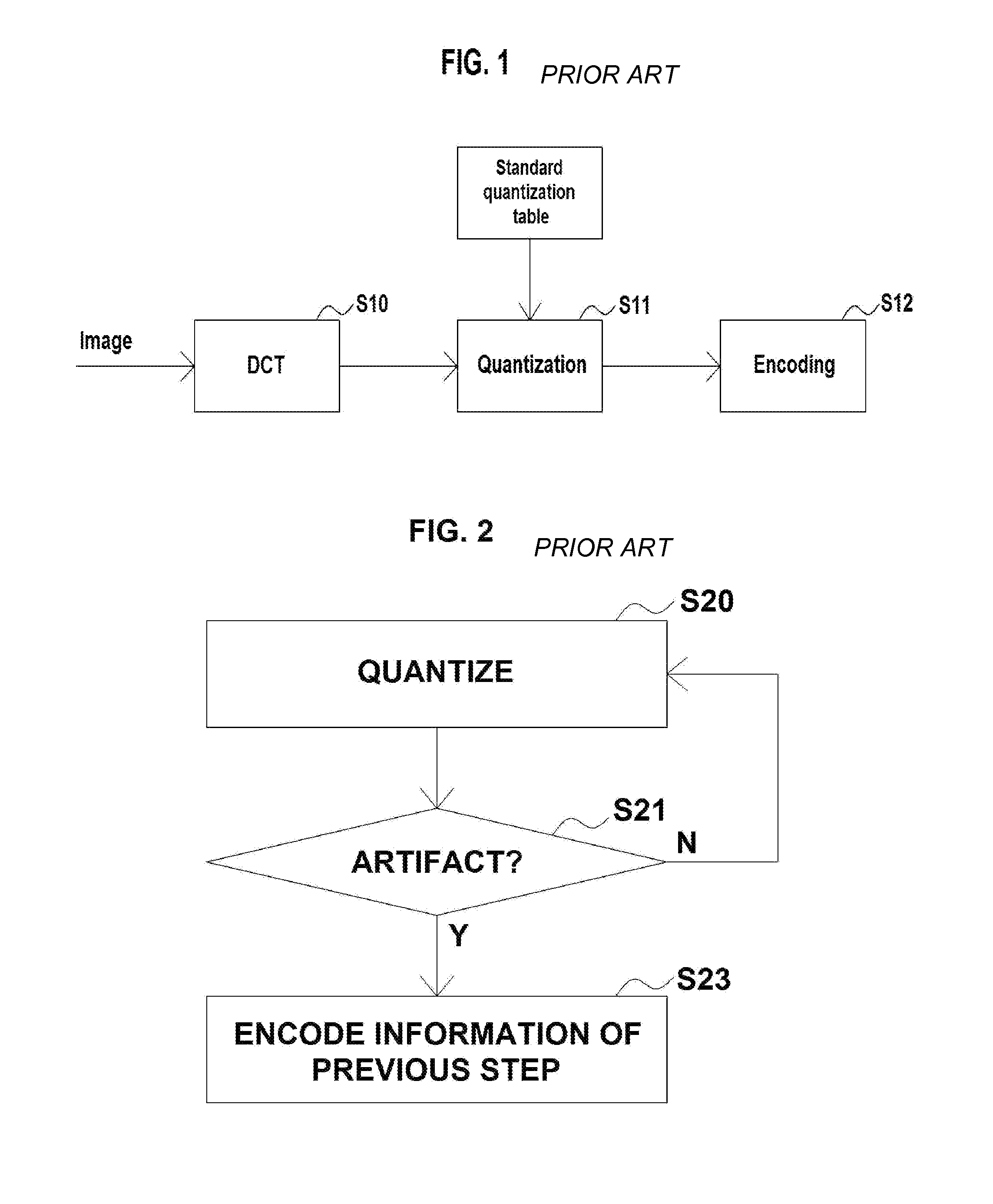
When the lossy-compression such as JPEG is carried out, most loss in information occurs during the quantization.
For example, although an increase in the image compression ratio (i.e. the increased quantization scale) has the effect of the decreased data size of the compressed image, this may significantly degrade the visual image quality, which is problematic.
In addition, although a decrease in the image compression ratio does not significantly degrade the image quality, the degree to which the data is compressed is insignificant, which is problematic.
However, such a compression method of the related art may be inefficient since quantization is carried out without considering whether the image to be compressed is a complicated image, the visual image degradation of which is relatively small even though much of the information is lost, or is a simple image, the visual image degradation of which is relatively great even though less of information is lost.
In addition, the compression speed is slow since the method iteratively determines whether or not to carry out the compression again or stop the compression once having carried out compression.
In addition, it is impossible to ensure that the final result of the compression be the optimum compression ratio, which is problematic.
This is because, although the result of the previous quantization step becomes the final result of the compression when an artifact occurs as a result of the quantization step that is finally carried out, the result of the previous quantization step does not guarantee that the image is compressed at the optimization compression ratio.

Method used


Image

  • Adaptive image compression system and method
  • Adaptive image compression system and method
  • Adaptive image compression system and method

Examples


Embodiment Construction

[0041]The present invention has other advantages associated with the operation of the present invention and objects that are realized by the practice of the present invention which will be apparent from, or are set forth in greater detail in the accompanying drawings, which are incorporated herein, and in the following Detailed Description of the Invention, which together serve to explain certain principles of the present invention.

[0042]Throughout the specification, it will be understood that, when an element is referred to as ‘transmitting’ a data to another element, the element not only can directly transmit the data to another element but also indirectly transmit the data to another element via at least one intervening element.

[0043]In contrast, when an element is referred to as ‘directly transmitting’ a data to another element, the element can transmit the data to another element without an intervening element.

[0044]The present invention will now be described more fully hereina...


PUM


Abstract

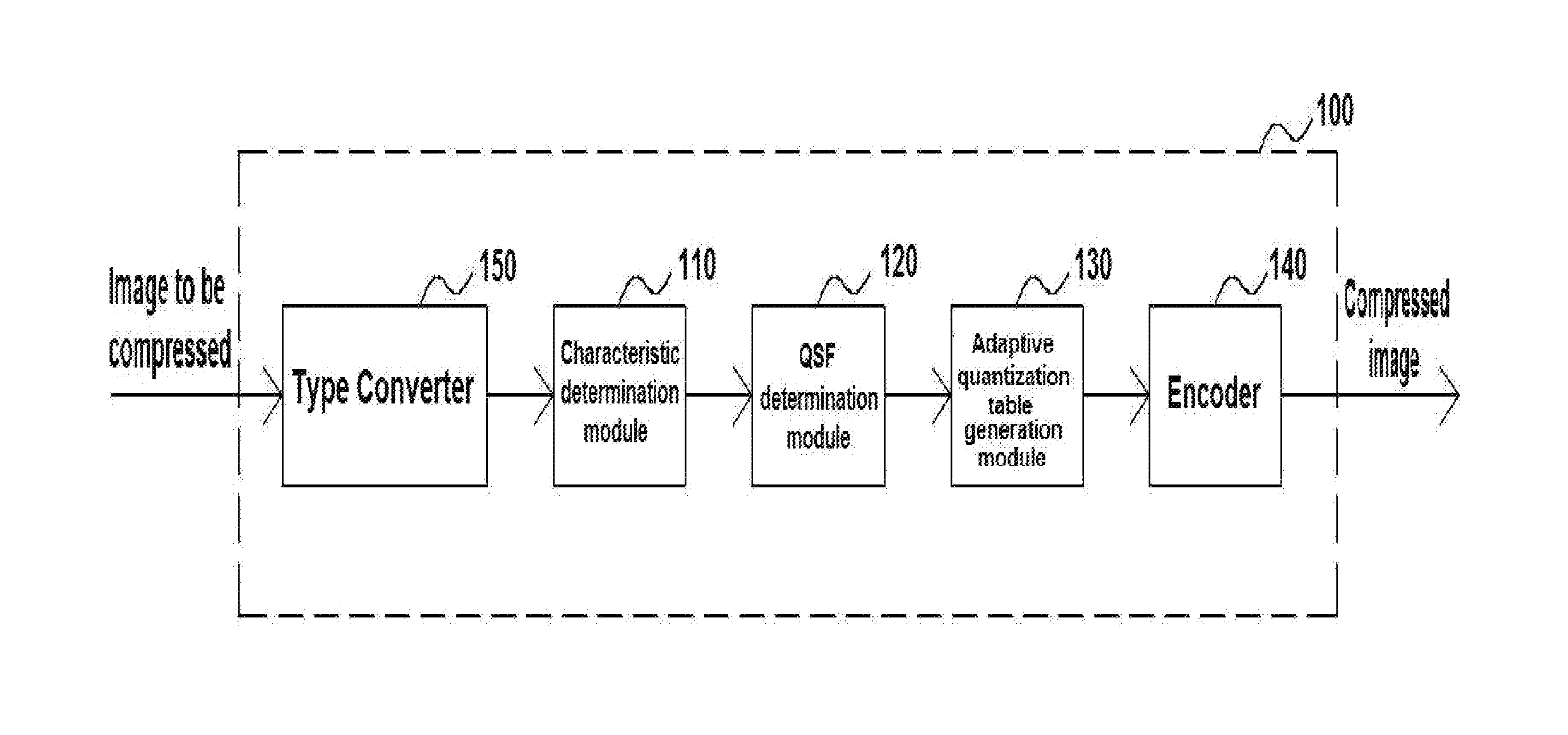
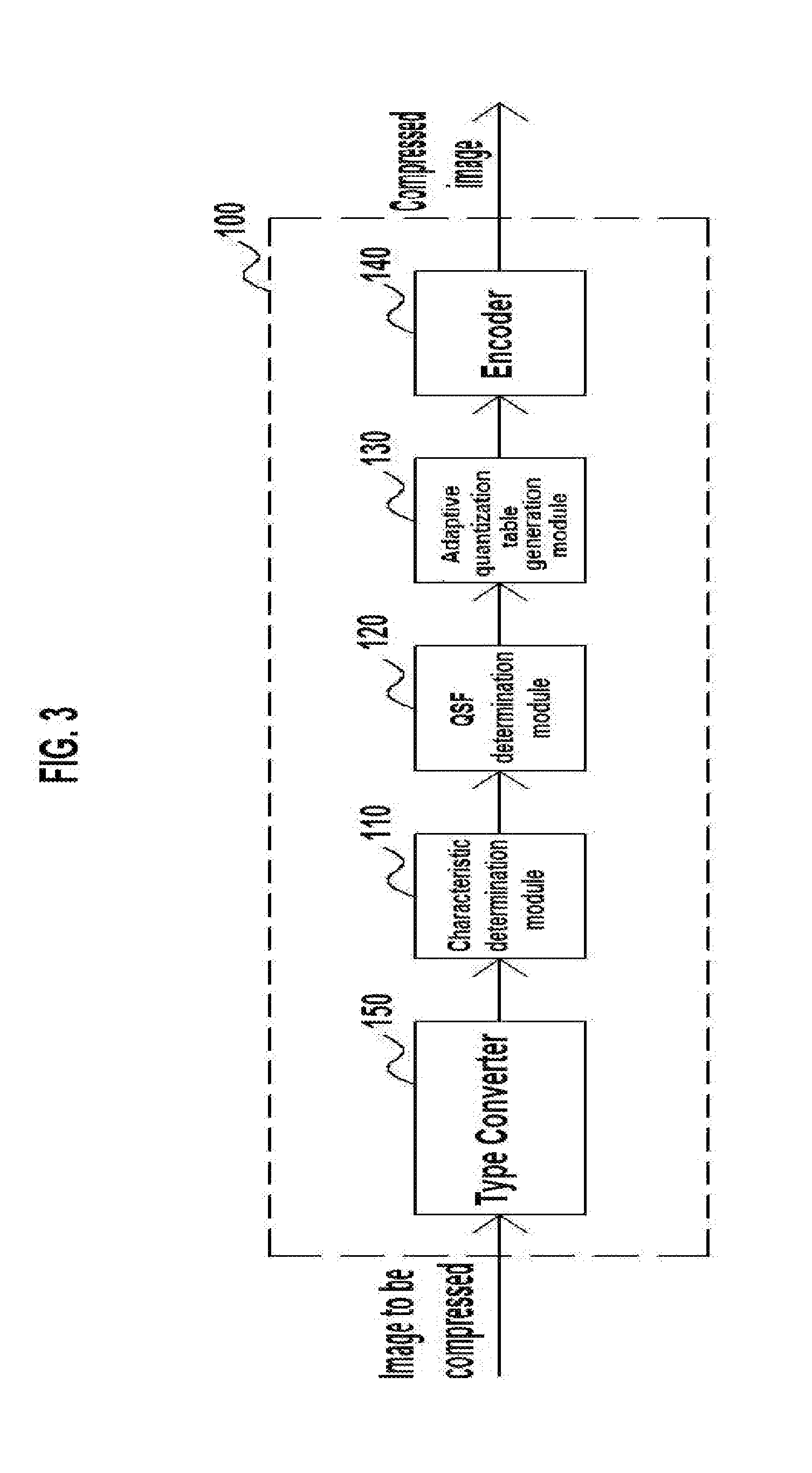
Provided are an adaptive image compression system and method. The adaptive image compression method includes a step of determining, at an adaptive image compression system, characteristics of an image that is to be compressed, a step of determining, at the adaptive image compression system, a quantization scale factor based on the characteristics of the image that is to be compressed, a step of generating an adaptive quantization table corresponding to the image that is to be compressed based on the determined quantization scale factor, and a step of encoding the image that is to be compressed using the generated adaptive quantization table.

Description

BACKGROUND OF THE INVENTION[0001]1. Field of the Invention[0002]The present invention relates to an adaptive image compression system and method, and more particularly, to an adaptive image compression system and method which can efficiently compress an image by analyzing the characteristics of the image to be compressed and determining a loss tolerance in which similar image quality can be maintained before compressing the image.[0003]2. Description of Related Art[0004]A variety of traditional image compression methods are well known in the art, in which joint photographic experts group (JPEG) compression is most popular and is widely used as the standard for compressing and expressing images.[0005]Although the technical principle of the present invention can be applied to all types of data compression methods, an application thereof to the JPEG will be described as a representative example.[0006]FIG. 1 is a block diagram schematically showing a method of generating a JPEG image of...

Claims


Application Information

Patent Timeline
IPC IPC(8): G06T9/00
CPCG06T9/00H04N19/176H04N19/126H04N19/14H04N19/154H04N19/625H04N19/00
Inventor WEE, YOUNG CHEULAHN, YOUNG HOONPARK, SUNG SOO
Owner QURAM
Learn More