
Data compression and reconstruction methods and apparatuses for hard copy device

a data compression and reconstruction technology, applied in the field of hard copy devices, can solve the problems of slow and variable compression speed of hard copy, low data compression ratio of hard copy devices with such high spatial resolution, etc., and achieve the effect of improving compression ratio and compression speed

Inactive Publication Date: 2002-07-04
S PRINTING SOLUTION CO LTD
View PDF3 Cites 11 Cited by
  • Summary
  • Abstract
  • Description
  • Claims
  • Application Information

AI Technical Summary

Benefits of technology

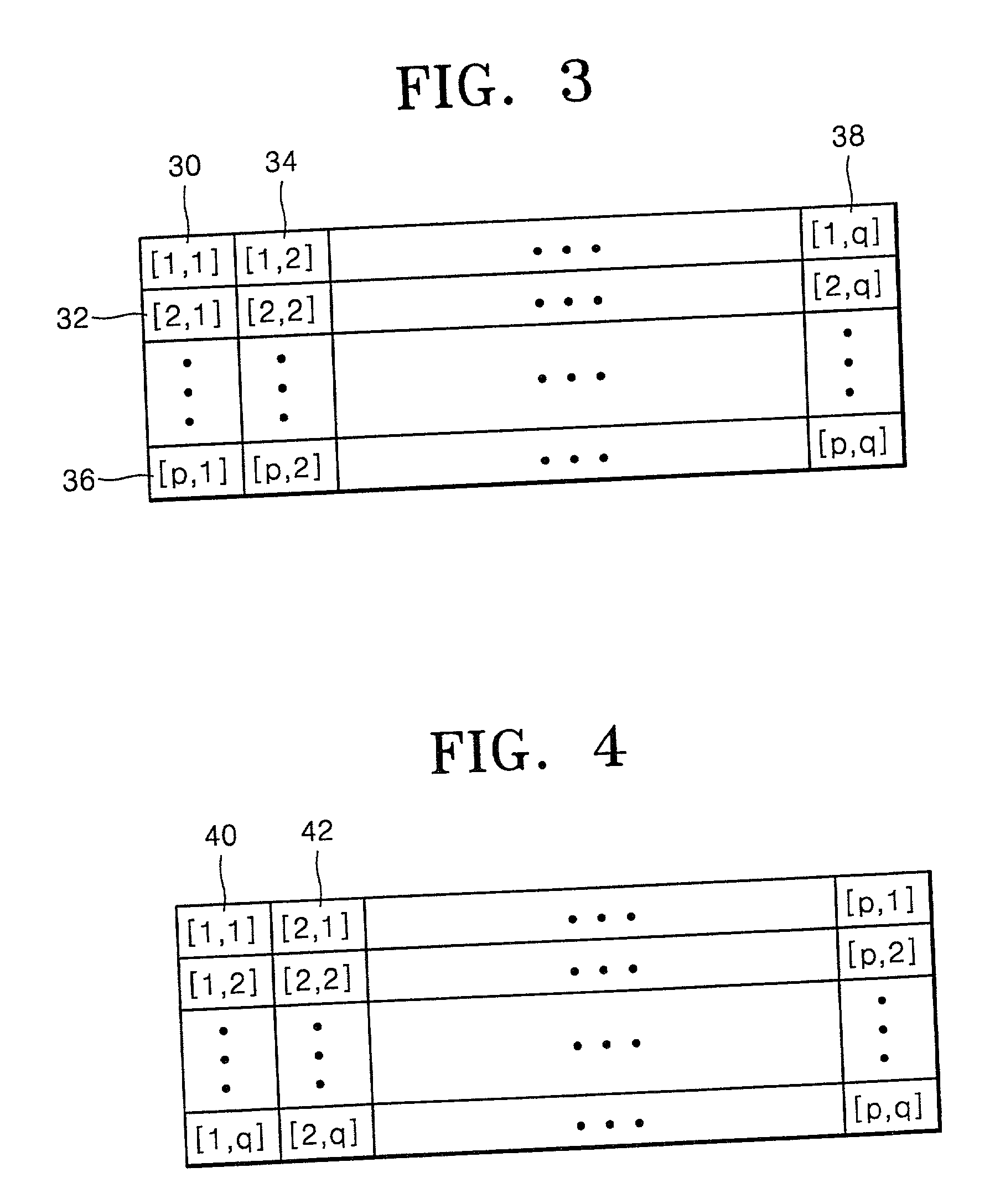
[0053] In FIG. 3, the neighboring row bytes, for example, [1,1] and [1,2] in the cells 30 and 34 among the row bytes [1,1], [1,2], . . . [1,q] in the cells 30, 34, . . . 38 at a row have neighboring memory addresses, and the distance, or the offset, between the neighboring column bytes, for example, [1,1] and [2,1] in the cells 30 and 32 among the [1,1], [2,1], . . . [p,1] in the cells 30, 32, . . . 36 at a column is very big. Here, the offset indicates a row width of a source image data bitmap and the distance between the two bytes in the memory. As the offset increases, addressing takes longer time.
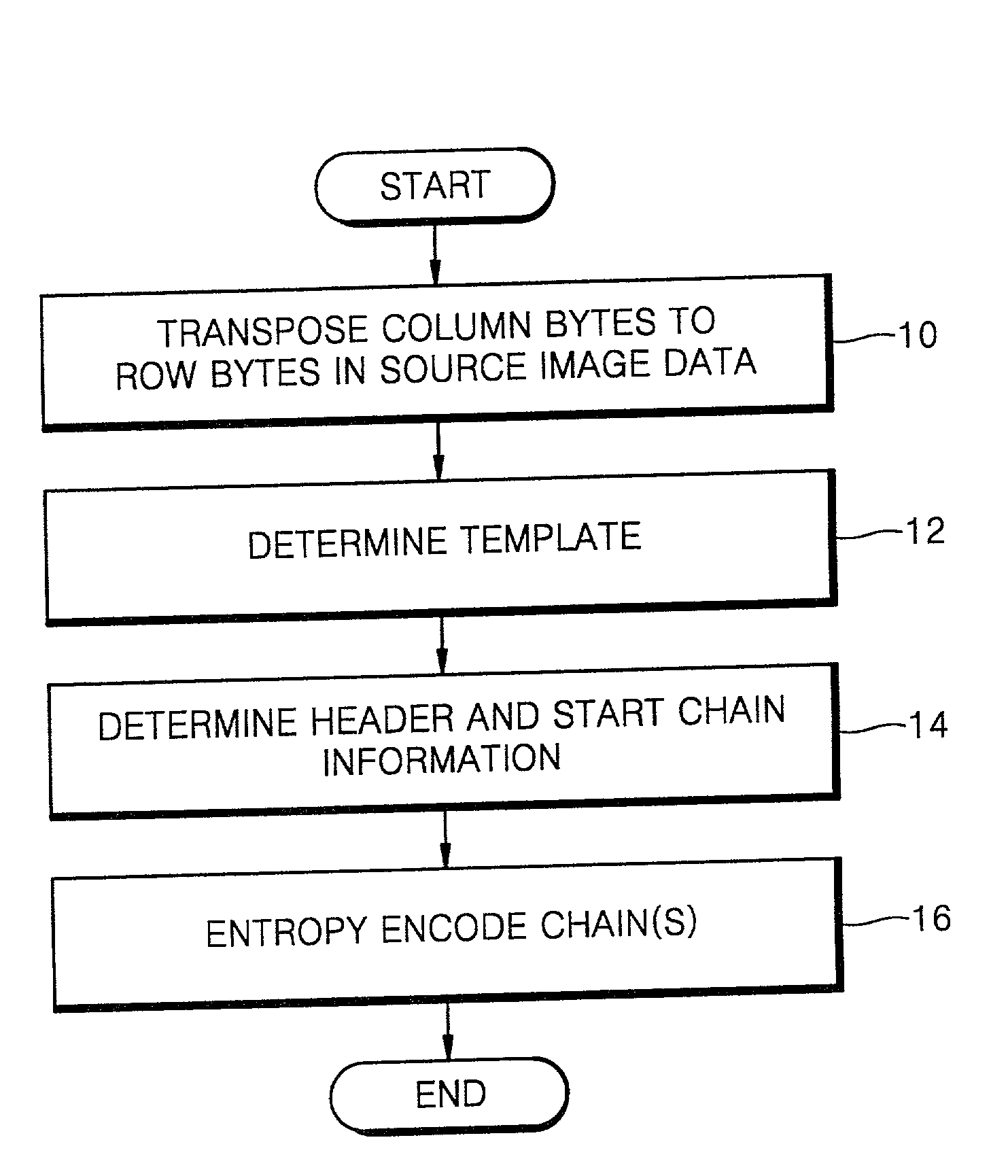
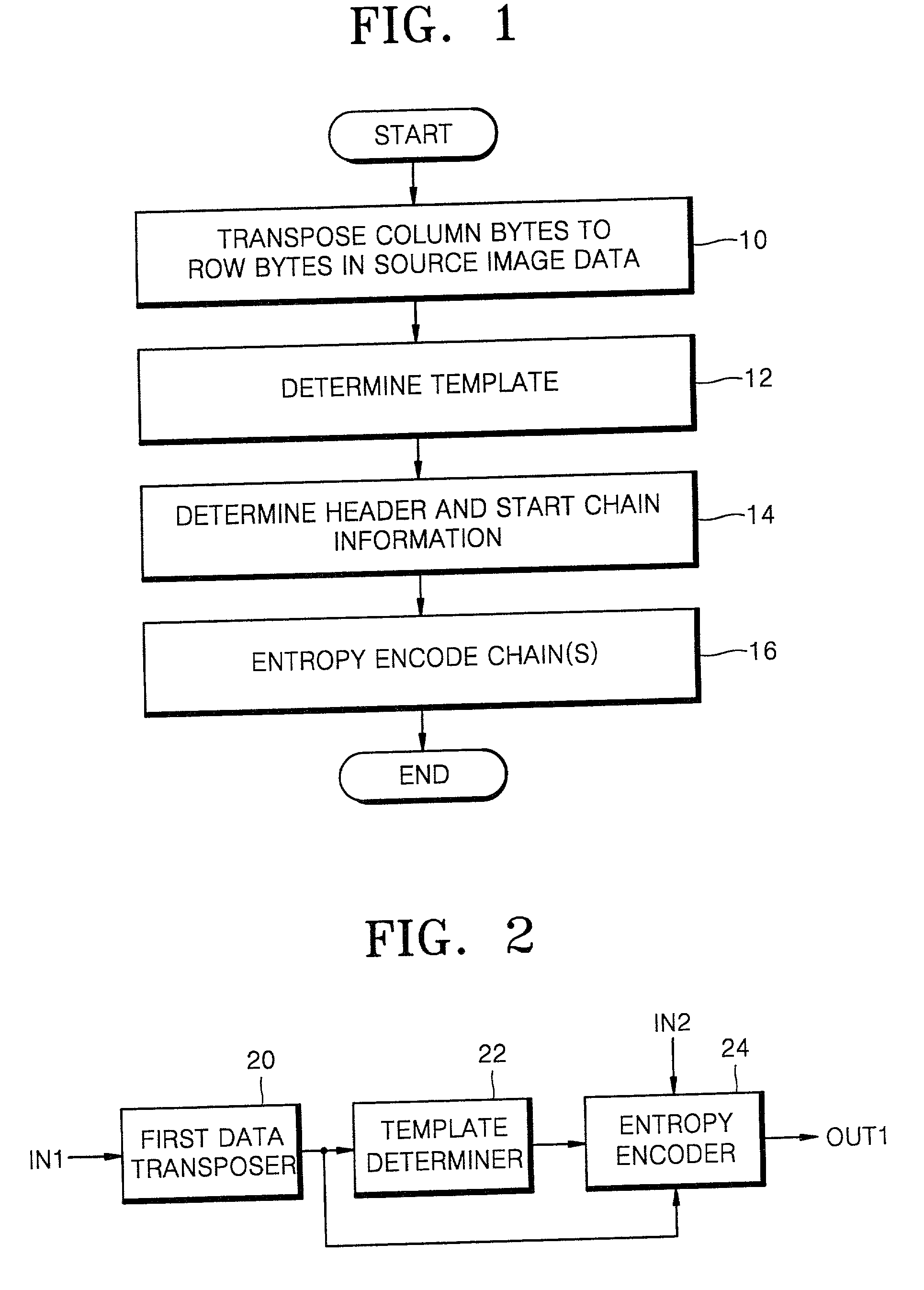
[0054] Transposition is performed in step 10 before encoding the source image data because of the following two reasons. First, when an image is screened by way of bilevel (by a halftone-machine), a source image is more randomized. Therefore, it is not necessary to randomize a transposed image. Second, the geometrical distance between neighboring bytes in FIG. 3 is 8 pixels in a horizontal direction and 1 pixel in a vertical direction, so vertically neighboring bytes are more similar than horizontally neighboring bytes. For example, the neighboring column bytes [1,1] and [2,1] in the cells 30 and 32 at a column in FIG. 3 are more similar than the neighboring row bytes [1,1] and [1,2] in the cells 30 and 34 at a row. Nevertheless, it takes longer to address the neighboring bytes [1,1] and [2,1] in the cells 30 and 32 at the column than to address the neighboring bytes [1,1] and [1,2] in the cells 30 and 34 at the row. Accordingly, the step 10 is performed so that the neighboring bytes [1,1] and [2,1] in the cells 30 and 32 at the column are positioned at memory addresses neighboring in the horizontal direction, as shown in FIG. 4. In other words, since the offset between the neighboring bytes [1,1 ] and [2,1] in the cells 30 and 32 at the column is larger than that of the neighboring bytes [1,1 ] and [1,2] in the cells 30 and 34 at the row, the step 10 is performed such that the bytes at the column are transposed to the bytes at the row to reduce the offset between the neighboring bytes [1,1] and [2,1] in the cells 30 and 32 at the column, thereby reducing the time necessary for addressing the neighboring column bytes.
[0082] Generally, most computers have better performance when processing 4-byte aligned data in units of 32 bits and when processing 2-byte aligned data in units of 16 bits. For this reason, chunk data and chain data are separated in source image data compressed according to the present invention, as shown in FIG. 13. The chunk data 144 is one-byte aligned data, but the chain data 142 may be 4-byte or 2-byte aligned data. Here, only the chain data is subjected to the alignment, but the chunk data is not subjected to the alignment.
[0116] As described above, in data compression and reconstruction methods and apparatuses for a hard copy device according to the present invention, transposition is performed before entropy decoding source image data, thereby improving the compression ratio, and the size of a template can be arbitrarily controlled, thereby improving the compression speed. The transposing of bytes can be referred to as a transposing process, for example. The encoding of data can be referred to as an encoding process, for example. The obtaining of a second count value can be referred to as an obtaining process, for example. The FIG. 3 shows the memory storing the source image data before transposition by first data transposer 20.

Problems solved by technology

However, hard copy devices having such high spatial resolution can have a low data compression ratio and a slow and unvariable compression speed for hard copy.

Method used


Image

  • Data compression and reconstruction methods and apparatuses for hard copy device
  • Data compression and reconstruction methods and apparatuses for hard copy device
  • Data compression and reconstruction methods and apparatuses for hard copy device

Examples


Embodiment Construction

[0049] While the present invention will be described more fully hereinafter with reference to the accompanying drawings, in which preferred embodiments of the present invention are shown, it is to be understood at the outset of the description which follows that persons of skill in the appropriate arts may modify the invention here described while still achieving the favorable results of this invention. Accordingly, the description which follows is to be understood as being a broad, teaching disclosure directed to persons of skill in the appropriate arts, and not as limiting upon the present invention.

[0050] Illustrative embodiments of the invention are described below. In the interest of clarity, not all features of an actual implementation are described. In the following description, well-known functions or constructions are not described in detail since they would obscure the invention in unnecessary detail. It will be appreciated that in the development of any actual embodiment ...


PUM


Abstract

Data compression and reconstruction methods and apparatuses for a hard copy device are provided. The data compression method of compressing source image data, which is used for hard copying a bilevel screened image and stored in a memory in units of bytes, for a hard copy device, includes the steps of transposing bytes at each column to bytes at each row in the source image data; and entropy encoding sequential chains, which include a current chain to be compressed and a chain or chains succeeding the current chain, or the current chain depending on whether a chain having the same value as that of the current chain exists in a dictionary composed of previous chains compressed before, and determining the result of the entropy encoding as the result of the compression. Neighboring bytes at each row have neighboring memory addresses. The offset of neighboring bytes at each column corresponds to the row width of the source image data. Start information containing information on a chain which compression is performed on the source image data starting from and header information are determined before the latter step and included in the result of the compression, and each chain is composed of at least two consecutive bytes at a row. Transposition is performed before entropy decoding source image data, thereby improving the compression ratio, and the size of a template can be arbitrarily controlled, thereby improving the compression speed.

Description

CLAIM OF PRIORITY[0001] This application makes reference to, incorporates the same herein, and claims all benefits accruing under 35 U.S.C. .sctn.119 from my application METHODS AND APPARATUSES FOR COMPRESSING AND RECOVERING DATA FOR HARD COPY APPARATUS filed with the Korean Industrial Property Office on Dec. 29, 2000 and there duly assigned Serial No. 86282 / 2000.[0002] 1. Technical Field[0003] The present invention relates to a hard copy device capable of printing on a transparent medium, and more particularly, to methods of compressing and reconstructing data used in a hard copy device and apparatuses for performing the methods.[0004] 2. Related Art[0005] The spatial resolution of a printer can be not very high, that is, 600 or 1200 dots per inch (dpi). On the contrary, the spatial resolution of hard copy devices can be very high up to about 12000 dpi. However, hard copy devices having such high spatial resolution can have a low data compression ratio and a slow and unvariable com...

Claims


Application Information

Patent Timeline
Patent Type & Authority Applications(United States)
IPC IPC(8): G06T9/00G06T9/20H04N1/415
CPCG06T9/20H04N1/415Y10S707/99942G06T9/00
Inventor BOTCHKAREV, SERAFIM
Owner S PRINTING SOLUTION CO LTD
Learn More