
Solenoid-controlled rotary intake and exhaust valves for internal combustion engines

a technology of internal combustion engines and valve timing, which is applied in the direction of oscillatory slide valves, machines/engines, non-mechanical valves, etc., can solve the problems of significant pressure loss in exhaust gasses, high heat stress, mechanical failure, etc., and achieve complex mechanical systems to change valve timing

Inactive Publication Date: 2014-02-27
TAYLOR JACK R
View PDF6 Cites 3 Cited by
  • Summary
  • Abstract
  • Description
  • Claims
  • Application Information

AI Technical Summary

Benefits of technology

The present invention is a solenoid-operated rotary valve used as a gas valve assembly in an IC engine. The valve is housed in a fixed housing and has a cylindrical valve body that rotates between an open position and a closed position. The valve body is connected to a mechanical lever and linkage that is controlled by an electrical solenoid. The valve can be used to control the flow of exhaust gas in an engine, and it offers a simplified and cost-effective design compared to conventional poppet valves. The valve also reduces exhaust system pressure drops and increases engine efficiency. Additionally, when used in an exhaust pipe, the valve body is exposed to high combustion temperatures, so it can be made from a heat-resistant material.

Problems solved by technology

Conventional poppet valves for IC engines have complex and costly camshafts and rocker arm mechanisms to open and close the intake and / or exhaust valves in timing with the reciprocating movement and position of the piston in the cylinder, and are subject to high heat stresses, leakage, and mechanical failure.
Also, significant pressure losses in the exhaust gasses are caused by valve stem and valve guide blockages in the exhaust pipe.
Several automobile companies have developed complex mechanical systems to change the valve timing.
Therefore, if a conventional electrical solenoid is used to open and close this valve, it would quickly overheat, because high electrical currents would be required at high engine speeds.
Additionally, the high amount of energy required to control a conventional electric solenoid to open and close the poppet valve reduces engine efficiency.

Method used


Image

  • Solenoid-controlled rotary intake and exhaust valves for internal combustion engines
  • Solenoid-controlled rotary intake and exhaust valves for internal combustion engines
  • Solenoid-controlled rotary intake and exhaust valves for internal combustion engines

Examples


Embodiment Construction

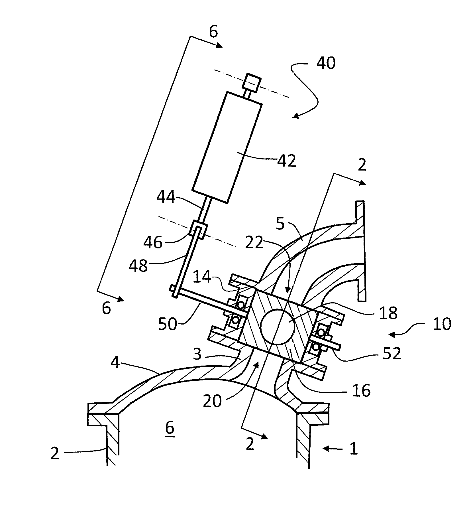
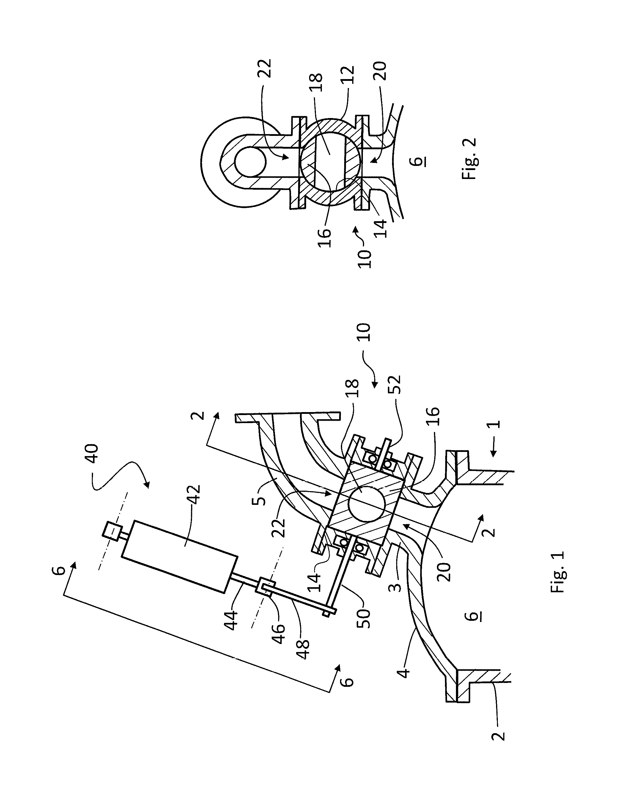
[0029]FIGS. 1-6 show a rotary valve and a rotary valve assembly for a cylinder of an internal combustion (IC) engine. The rotary valve and rotary valve assembly can be employed as an air inlet valve or as a combustion air exhaust valve.

[0030]The engine cylinder 1 includes a cylinder wall 2 and a head 4 that define a cylinder space 6. The rotary valve 10 is mounted to an inlet gas pipe 3 of the cylinder head 4 having a gas inlet passage 20, and to an outlet gas pipe 5 having a gas outlet passage 22.

[0031]As shown in FIG. 5, the rotary valve 10 includes a fixed housing 12 having a cylindrical bore 14 arranged on an axis 100, an inlet port 13 intersecting bore 14 substantially perpendicularly, and an outlet port 15 intersecting bore 14 substantially perpendicularly, wherein bore 14 and inlet / outlet ports 13, 15 provide a fluid communication through the housing 12. The gas inlet passage 20 and the gas outlet passage 22 communicate fluidly with the inlet port 13 and the outlet port 15, r...


PUM


Abstract

A solenoid-operated air inlet or combustion exhaust valve, for a rotary exhaust valve assembly or a sliding plate valve. The rotary exhaust valve has a fixed housing with a cylindrical bore in fluid communication with an air inlet port and / or a combustion gas outlet port, and a cylindrical valve body that rotates within the bore of the fixed housing. The valve body has a gas passage transverse to the axis. The sliding plate valve has a fixed housing with a cylindrical bore in fluid communication with a gas inlet passage and a gas outlet passage, and a plate between the gas inlet passage and the gas outlet passage with an aperture, moving between open and closed positions. An electric linear solenoid reciprocates linearly and operates the sliding plate valve or the rotary valve, directly or through a lever to rotate the rotary valve body, between the open and closed positions.

Description

CROSS-REFERENCE TO RELATED APPLICATIONS[0001]This application claims the benefit of U.S. provisional patent application 61 / 691,842, filed Aug. 22, 2012, and of U.S. provisional patent application 61 / 691,843, filed Aug. 22, 2012, the disclosures of which are incorporated by reference in their entirety.FIELD OF THE INVENTION[0002]The present invention is in the field of internal combustion (IC) engines, and more particularly high efficiency IC engines, and to intake and exhaust valves therefore.BACKGROUND OF THE INVENTION[0003]Conventional poppet valves for IC engines have complex and costly camshafts and rocker arm mechanisms to open and close the intake and / or exhaust valves in timing with the reciprocating movement and position of the piston in the cylinder, and are subject to high heat stresses, leakage, and mechanical failure. Also, significant pressure losses in the exhaust gasses are caused by valve stem and valve guide blockages in the exhaust pipe.[0004]The ability to have ra...

Claims


Application Information

Patent Timeline
Patent Type & Authority Applications(United States)
IPC IPC(8): F02B77/00
CPCF02B77/00F01L7/02F01L7/06F01L9/20F02M63/0017F16K31/0675
Inventor TAYLOR, JACK R.
Owner TAYLOR JACK R
Learn More