
Organic light-emitting display apparatus and method of manufacturing the same

a technology of light-emitting display and organic light, which is applied in the direction of vacuum evaporation coating, thermoelectric devices, coatings, etc., can solve the problems of long manufacturing time, inconvenient manufacturing of organic light-emitting display devices using a large mother glass, and inconvenient manufacturing of large mother glass, so as to prevent a reduction in luminescent efficiency and improve the device properties of transistors and capacitors.

Active Publication Date: 2014-02-20
SAMSUNG DISPLAY CO LTD
View PDF7 Cites 8 Cited by
  • Summary
  • Abstract
  • Description
  • Claims
  • Application Information

AI Technical Summary

Benefits of technology

This patent aims to improve the efficiency, lifetime, and productivity of organic light-emitting display apparatuses by introducing a method of manufacturing that allows for patterned deposition of the organic light-emitting layer, increased processing speed, reduced number of masks, and prevention of total reflection to enhance luminescent efficiency. Additionally, the refraction conversion layer serves as a gate insulating layer of a transistor and / or a dielectric layer of a capacitor to improve device properties.

Problems solved by technology

However, the deposition method using such an FMM presents difficulties in manufacturing large organic light-emitting display devices using a large mother glass.
Such disadvantages are not conducive to the recent trend towards high-definition patterns.
Moreover, processes of aligning a substrate and an FMM to closely contact each other, performing deposition thereon, and separating the FMM from the substrate are time-consuming, resulting in a long manufacturing time and low production efficiency.

Method used


Image

  • Organic light-emitting display apparatus and method of manufacturing the same
  • Organic light-emitting display apparatus and method of manufacturing the same
  • Organic light-emitting display apparatus and method of manufacturing the same

Examples


Embodiment Construction

[0055]Reference will now be made in detail to the present embodiments of the present invention, examples of which are illustrated in the accompanying drawings, wherein like reference numerals refer to the like elements throughout. The embodiments are described below in order to explain aspects of the present invention by referring to the figures. As used herein, the term “and / or” includes any and all combinations of one or more of the associated listed items. Expressions such as “at least one of,” when preceding a list of elements, modify the entire list of elements and do not modify the individual elements of the list.

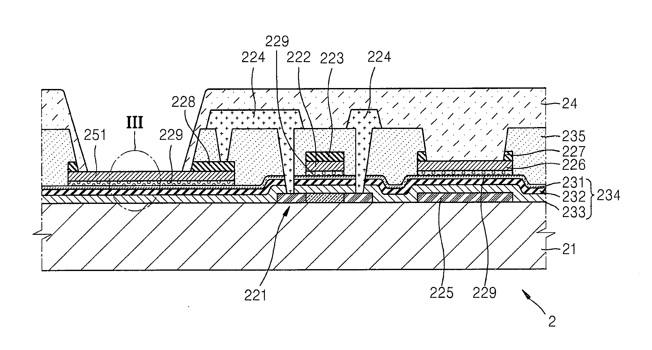
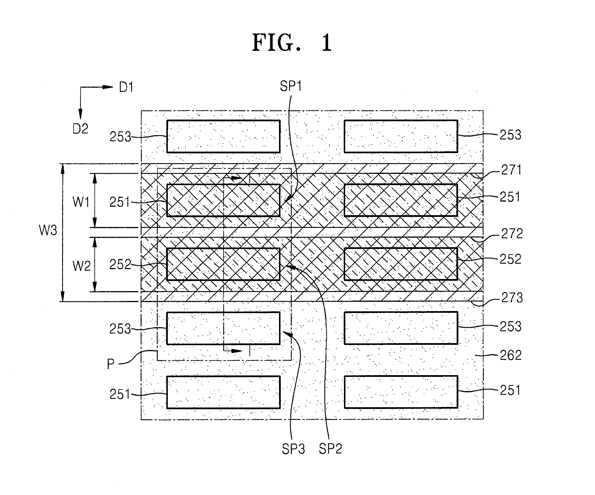
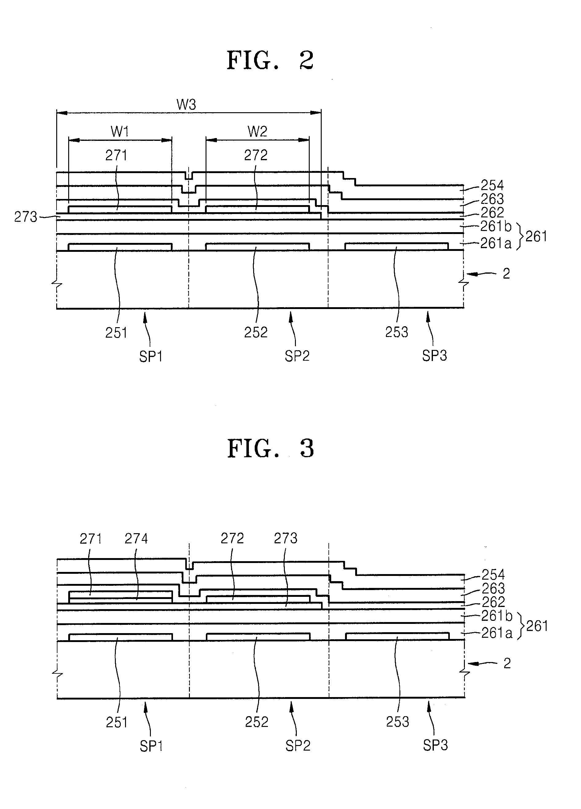
[0056]FIG. 1 is a plan view of a portion of an organic light-emitting display apparatus according to an embodiment of the present invention. FIG. 2 is a cross-sectional view of the organic light-emitting display apparatus taken along line I-I of FIG. 1, according to an embodiment of the present invention. For convenience of description, FIG. 1 only shows first pixel e...


PUM

PropertyMeasurementUnit
Thicknessaaaaaaaaaa
Transparencyaaaaaaaaaa
Transport propertiesaaaaaaaaaa

Abstract

An organic light-emitting display apparatus includes a substrate comprising pixels, each of which comprises a first sub-pixel, a second sub-pixel, and a third sub-pixel, and a plurality of pixel electrodes independently formed for respective sub-pixels; a first common layer commonly formed on the pixels; first lines covering first sub-pixels arranged in a first direction, wherein the first lines comprise a first organic light-emitting layer; a plurality of second lines covering second sub-pixels arranged in the first direction, wherein the second lines comprise a second organic light-emitting layer differing from the first organic light-emitting layer; a second common layer commonly formed on the plurality of pixels, wherein the second common layer comprises a third organic light-emitting layer differing from the first organic light-emitting layer and the second organic light-emitting layer; a third common layer commonly formed on the pixels; and an opposite electrode commonly formed on the pixels.

Description

CROSS-REFERENCE TO RELATED PATENT APPLICATION[0001]This application claims priority to and the benefit of Korean Patent Application No. 10-2012-0090096, filed on Aug. 17, 2012, in the Korean Intellectual Property Office, the disclosure of which is incorporated herein in its entirety by reference.BACKGROUND[0002]1. Field of the Invention[0003]The following description relates to an organic light-emitting display apparatus and a method of manufacturing the same.[0004]2. Description of the Related Art[0005]An organic light-emitting display device includes intermediate layers (including an emission layer) disposed between electrodes that are arranged opposite to (arranged to face) each other. The electrodes and the intermediate layers may be formed using various methods, one of which is an independent deposition method. When an organic light-emitting display device is manufactured by using the deposition method, a fine metal mask (FMM) having the same pattern as that of an organic layer...

Claims


Application Information

Patent Timeline
IPC IPC(8): H01L51/52
CPCH01L51/5203C23C14/042C23C14/12C23C14/24C23C14/56H10K59/35H10K59/123H10K59/1201H10K71/00H10K59/876H10K59/879H10K50/171H10K2102/351H10K50/13H10K50/156H10K50/852H10K50/858
Inventor CHANG, SEUNG-WOOK
Owner SAMSUNG DISPLAY CO LTD
Learn More