
Muliti-effect distillation device

a multi-effect distillation and spiral technology, applied in the direction of distillation in boilers/stills, chemistry apparatus and processes, separation processes, etc., can solve the problems of contaminated distilled water, difficult design and manufacture, and air tightness of the sides of the distiller, etc., to achieve easy manufacturing multi-effect distillation, high efficiency, and low production cost

Inactive Publication Date: 2014-02-13
HUANG BIN JUINE
View PDF5 Cites 11 Cited by
  • Summary
  • Abstract
  • Description
  • Claims
  • Application Information

AI Technical Summary

Benefits of technology

The present invention aims to provide a practical, efficient, simple, low-cost, and easy-to-manufacture multi-effect distillation device. The invention includes the sealing of the gap between the top and bottom to prevent leaks of water vapor. Additionally, the distiller has a heat recycling system to recycle the excess heat of the distilled water and drained waste water. The system includes pipes with good thermal contact with the water, allowing the heat to be recycled through heat exchange. The invention also has a layered structure, with the central circle having the highest height and the outermost layer having the highest height.

Problems solved by technology

Due to the diffusive-type distillation device's compact and unique structure, the design and manufacture is extremely difficult.
One of the most complex issues during the manufacture process is to maintain the small distance between the wick of one distiller and the condensing surface of the next distiller.
If there is contact between the two surfaces, the distilled water might be contaminated by the undistilled water or vice versa.
Another issue is the air tightness of the sides of the distillers.
If there is any slight detachment, the efficiency of the device will decrease.
The common method is to press the sides, but this will increase weight and complexion of the device.
However, this increases the difficulty of future changing of materials, and also increases heat resistance.
The wick, allowing in-flowing water to flow thoroughly to stay wet uniformly, and the air tightness and strength of the structure, which makes the design and production become more difficult.
However, this is too complicated and the common method is to mix the waters together and then recycle the heat.
This method obviously does not utilize the heat to the maximum.
Due to the above reasons, conventional distillation device has always been too complex in design and manufacture, and therefore less practical.

Method used


Image

  • Muliti-effect distillation device
  • Muliti-effect distillation device
  • Muliti-effect distillation device

Examples


Embodiment Construction

[0044]Detail description of present invention with corresponding drawings is as following:

[0045]Refer FIGS. 2-7, which reveal present invention is composed of:

[0046]At least one thin laminated distiller 1,

[0047]Characterized by:

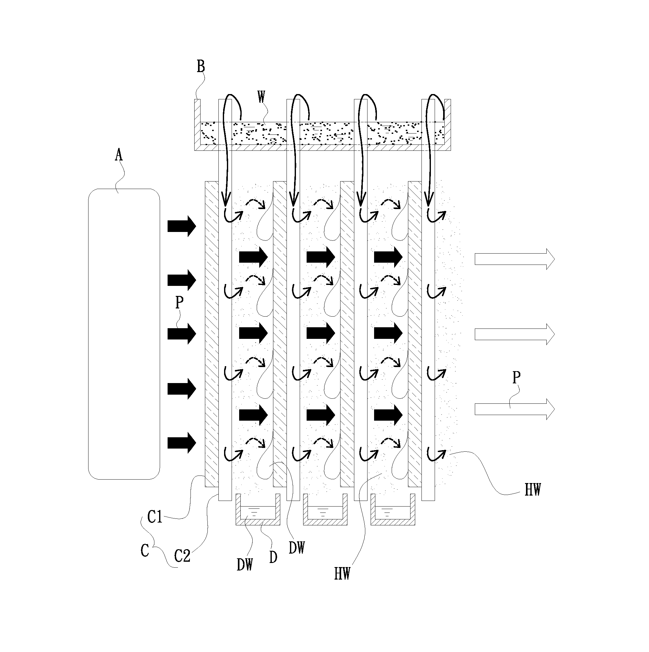
[0048]Said distiller 1 is constructed in a spiral structure which is tangled from a central circle with vertical axis to outer; the inner surface of the tangled distiller is condensing surface 11 which is for condensation of vapor of water HW, condensed distilled water DW is drained from underneath of said condensing surface 11. the outer surface of the tangled distiller is attached with a piece of wick 12 which is made of capillary materials, undistilled water W enters from above of the wick 12, than be absorbed and distributed by said wick 12; some of the water absorbed on said wick 12 is evaporated into the vapor of water HW, and unevaporated water in said wick 12 become the drained waste water XW which is drained from underneath of said wick 12; there is ...


PUM


Abstract

Present invention is a practical, highly efficient, structurally simple, low production cost, easy to manufacturing, and inexpensive multi-effect distillation device composed of thin-laminated distiller which is tangled into spiral and becomes layers of centric circle; one side of surface of said distiller is condensing surface which is for condensation of vapor of water, condensed distilled water is drained from underneath of said condensing surface, another side of said distiller is attached with a piece of wick which is made of capillary materials, undistilled water enters from above of the wick, than be absorbed and distributed by said wick. Some of the water absorbed on said wick is evaporated into the vapor of water. There is a gap between condensing surface and wick of each adjacent layers. The top and bottom of said gap is sealed to prevent leaking of the vapor of water.

Description

BACKGROUND OF THE INVENTION[0001]1. Field of Invention[0002]The present invention relates to an apparatus for distilling water and, more particularly, to a spiral multi-effect distillation device.[0003]2. Related Prior Art[0004]A diffusive type multi-effect distillation device is a highly effective, heat-driven distillation system. Dunkle [M. Telkes, Solar still construction, US Department of the Interior, Office of Saline Water Research and Development, Progress Report No. 33, 1959.] was the first to mention the theory of multiple-effect diffusion still (MEDS) in 1959. Referring to FIG. 1, the conventional diffusive multi-effect distillation device consisted of multiple distillers (C) extending parallel to one another. Distillers (C) are in laminate form, one side was used as a condensing surface (C1), where vapor would condense and the distilled water (DW) would drop down and be collected underneath said condensing surface C1. The other side would be attached to a capillary materi...

Claims


Application Information

Patent Timeline
Patent Type & Authority Applications(United States)
IPC IPC(8): B01D3/02
CPCB01D3/065
Inventor HUANG, BIN-JUINECHANG, SHIH-LIN
Owner HUANG BIN JUINE
Learn More