
Method for Achieving An Efficient Statistical Optimization of Integrated Circuits

Inactive Publication Date: 2014-02-06
GLOBALFOUNDRIES INC
View PDF0 Cites 7 Cited by
  • Summary
  • Abstract
  • Description
  • Claims
  • Application Information

AI Technical Summary

Benefits of technology

The present invention provides a system and method for closing timings in the presence of manufacturing and process variations. This involves inspecting timing violations and determining the best type of move or set of moves to fix each violation. This results in a more efficient timing closure procedure, fewer calculations, and designs with fewer timing violations, lower area, and lower power. The invention also addresses simultaneous violations at all relevant corners of the space of variations.

Problems solved by technology

Some moves improve the timing characteristics of the design and others make timing worse, so that the timing closure process is often “timing driven”, meaning that the static timer is queried to determine which changes improve the design and which do not.
Manufacturing and environmental variations significantly complicate the timing closure.
Both conventional methods suffer from significant drawbacks.
In the aforementioned first method, the computer run time of updating timing and answering timing queries after each design change can be prohibitive, because millions of changes can be attempted in a single optimization run and timing queries must be answered every single time.
A second drawback is that each proposed change provides a different amount of benefit at different process corners.
If the multi-corner or statistical timing must be repeated to evaluate the benefit of each proposed change, the computational burden can become overwhelming.
If single corner timing is used to guide the optimization, then the timing violations at other corners may not be addressed and may in fact get worse.
Thus, the optimization may improve the timing at the single corner considered, but make timing worse at other corners, and may “ping pong” back and forth without making any real progress.
This drawback of prior art embodiments highlights the difficulty of timing closure in the presence of variations.
A third weakness of prior art methods is that there is no easy way to decide which type of move is most effective in any given situation.
Presently, violations that benefit from a different order of moves cannot be achieved with conventional methods.
As a result, conventional embodiments are inefficient due to applying the same order of types of moves to all the timing violations.
This inefficiency manifests itself as longer run times and sub-optimal results in terms of timing, power and area of the integrated circuit.
The heuristic ordering of moves makes the optimization results inconsistent, untrustworthy and subject to chance.
Other conventional methodologies also suffer from another significant drawback.
Therefore, there is no clear timing guidance for the rest of the moves in the “batch” of moves.
As in this conventional embodiment, there is no guarantee that various corners or portions of the space of manufacturing variations will have fixed timing violations.
As previously stated, there is no intuitive approach for which type of change will be most beneficial in any given situation.
In many instances, they are limited by the use of heuristic methods to optimize moves in various different orders to fix the timing violations.
The heuristic order is applied to all the timing violations, which is wasteful because different timing violations benefit from different types of moves, and trying moves in the same order across all the timing violations, which is inefficient.
In view of these and other reasons, conventional embodiments have failed to achieve timing closure in the presence of manufacturing and environmental variations, and suffer from significant drawbacks.
Accordingly, methods have been proposed in the literature, but generally have not been practiced in industry.

Method used


Image

  • Method for Achieving An Efficient Statistical Optimization of Integrated Circuits
  • Method for Achieving An Efficient Statistical Optimization of Integrated Circuits
  • Method for Achieving An Efficient Statistical Optimization of Integrated Circuits

Examples


example 1

[0034]Consider an early mode timing test slack of S=−5+2ΔX1−ΔX2+ΔR in a timing methodology in which there are two global sources of variation, and worst-case projection is used for timing sign-off The worst-case projection of slack S is −5+2(−3)−(3)+(−3)=−17 ps which is obtained by projecting each source of variation to either plus or minus 3 sigma, whichever makes the slack worse (smaller). Consider a delay pad cell whose goodness has been pre-characterized as D1=7−ΔX1+ΔX2+ΔR. Then, the following equation for a slack after inserting one delay pad cell is provided, wherein: S+D1=2+ΔX1+√{square root over (2)}ΔR with a worst-case projection of −5.2 ps. After inserting two delay pad cells one obtains S+2D1−9+ΔX2+√{square root over (3)}ΔR with a worst-case projection of +0.9 ps, which would fix the timing violation. If three pad cells were to be inserted, one would obtain S+3D1=16−ΔX1+2ΔX22ΔR with a worst-case projection of +1.0 ps. Thus, it is seen in the present example that one can d...

example 2

[0035]Consider a timing test slack of S=−5+2ΔX1−ΔX2+ΔR with a worst-case projection of −17 ps as before. Consider a situation where there are two delay pad cells available. The first cell has a goodness function D1=4−ΔX1+ΔX2+ΔR, and is a relatively inexpensive cell to use in terms of area or power. The other pad cell has a goodness function D2=7−ΔX1+ΔR and is relatively expensive in terms of area or power. Using algebra, one finds that S+D1+D2=6+√{square root over (3)}ΔR with a worst-case projection of +0.9 ps, implying that in this instance, the combination of one cheap and one costly pad cell will succeed and achieve a positive slack. The example demonstrates the timing benefits of sensitivity cancellation since the combination of one of each of the two types of pad cells completely cancels out global variation in the slack, leaving only independently random variation. This allows for an efficient fix to the original timing violation.

[0036]General formulation: The two prior exampl...


PUM


Abstract

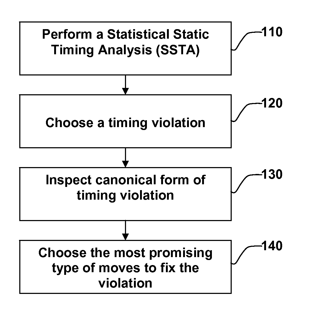
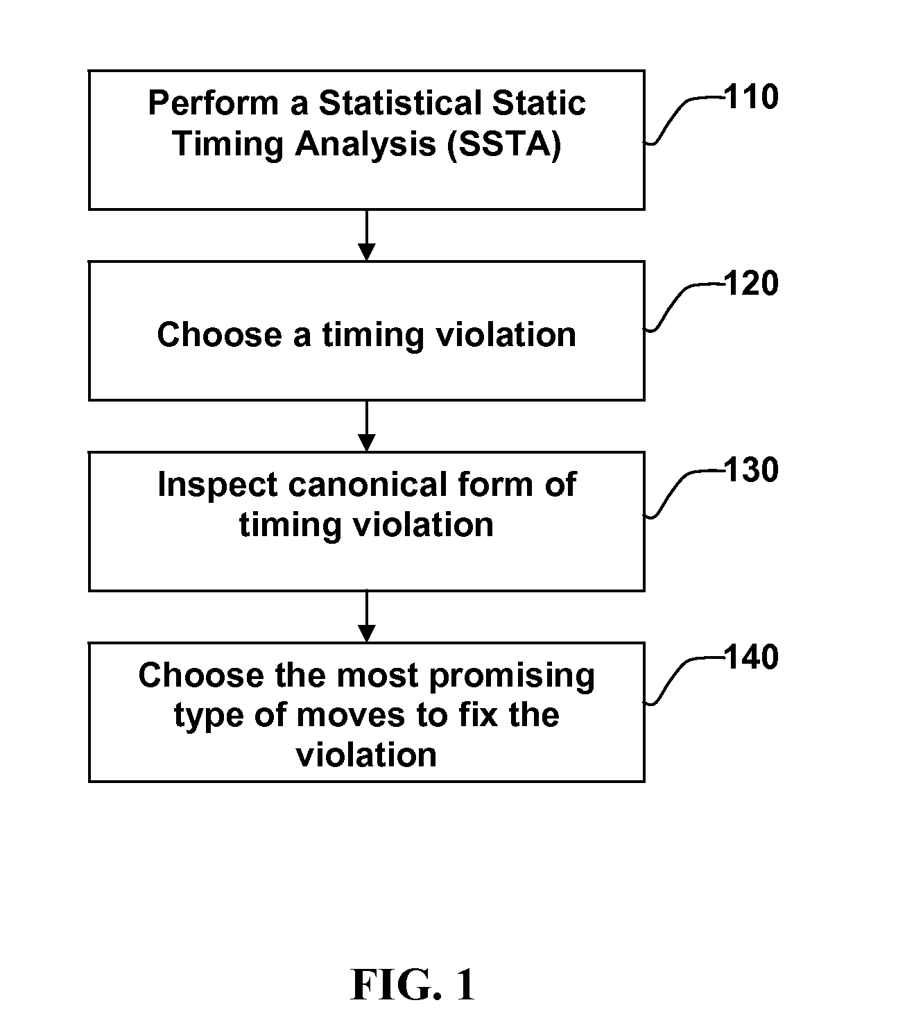
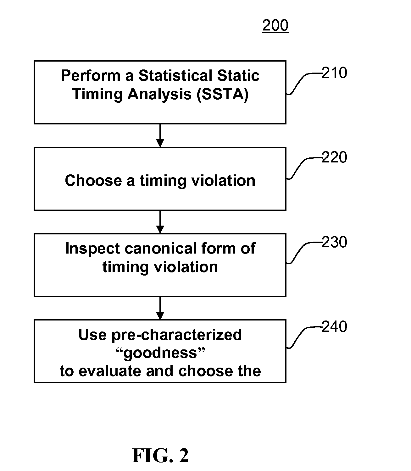
Method for performing timing closure of integrated circuits in the presence of manufacturing and environmental variations. The starting design is analyzed using statistical static timing analysis to determine timing violations. Each timing violation in its statistical canonical form is examined. In a first aspect of the invention, the canonical failing slack is inspected to determine what type of move is most likely to fix the timing violation taking into account all relevant manufacturing and environmental variations. In a second aspect of the invention, pre-characterized moves such as insertion of delay pad cells are evaluated for their ability to fix the timing violation without triggering timing, and the best move or set of moves is selected.

Description

FIELD OF THE INVENTION[0001]The present invention relates to the design and optimization of integrated circuits. More particularly, it relates to Electronic Design Automation of integrated circuits, and yet, more specifically, to a system and methods of achieving timing closure during the design of integrated circuits while taking manufacturing and environmental variations into account.BACKGROUND OF THE INVENTION[0002]Timing closure refers to the process of making changes to an initial integrated circuit design to get rid of timing violations. Typically, a static timing analysis software tool is employed to determine all the timing violations. Changes are made to improve the design and static timing analysis is iteratively invoked until all violations have been addressed. These changes are also referenced to as “moves.” Making moves to improve the timing of the circuit will be referred hereinafter as optimization.[0003]Examples of changes made to achieve timing closure include buffe...

Claims


Application Information

Patent Timeline
IPC IPC(8): G06F17/50
CPCG06F30/3312
Inventor VISWESWARIAH, CHANDRAMOULIFLUHR, ERICSHUMA, STEPHEN G.SINHA, DEBJITWOOD, MICHAEL H.
Owner GLOBALFOUNDRIES INC
Learn More