
Telecentric Scale Projection System for Real-Time In-Situ Surgical Metrology

a projection system and surgical metrology technology, applied in the field of telecentric scale projection system for real-time in-situ surgical metrology, can solve the problem of limited access to the surgical si

Inactive Publication Date: 2014-01-30
TYCO HEALTHCARE GRP LP
View PDF23 Cites 90 Cited by
  • Summary
  • Abstract
  • Description
  • Claims
  • Application Information

AI Technical Summary

Benefits of technology

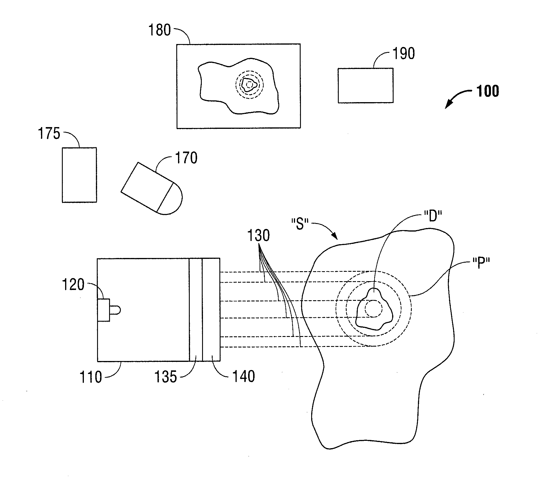
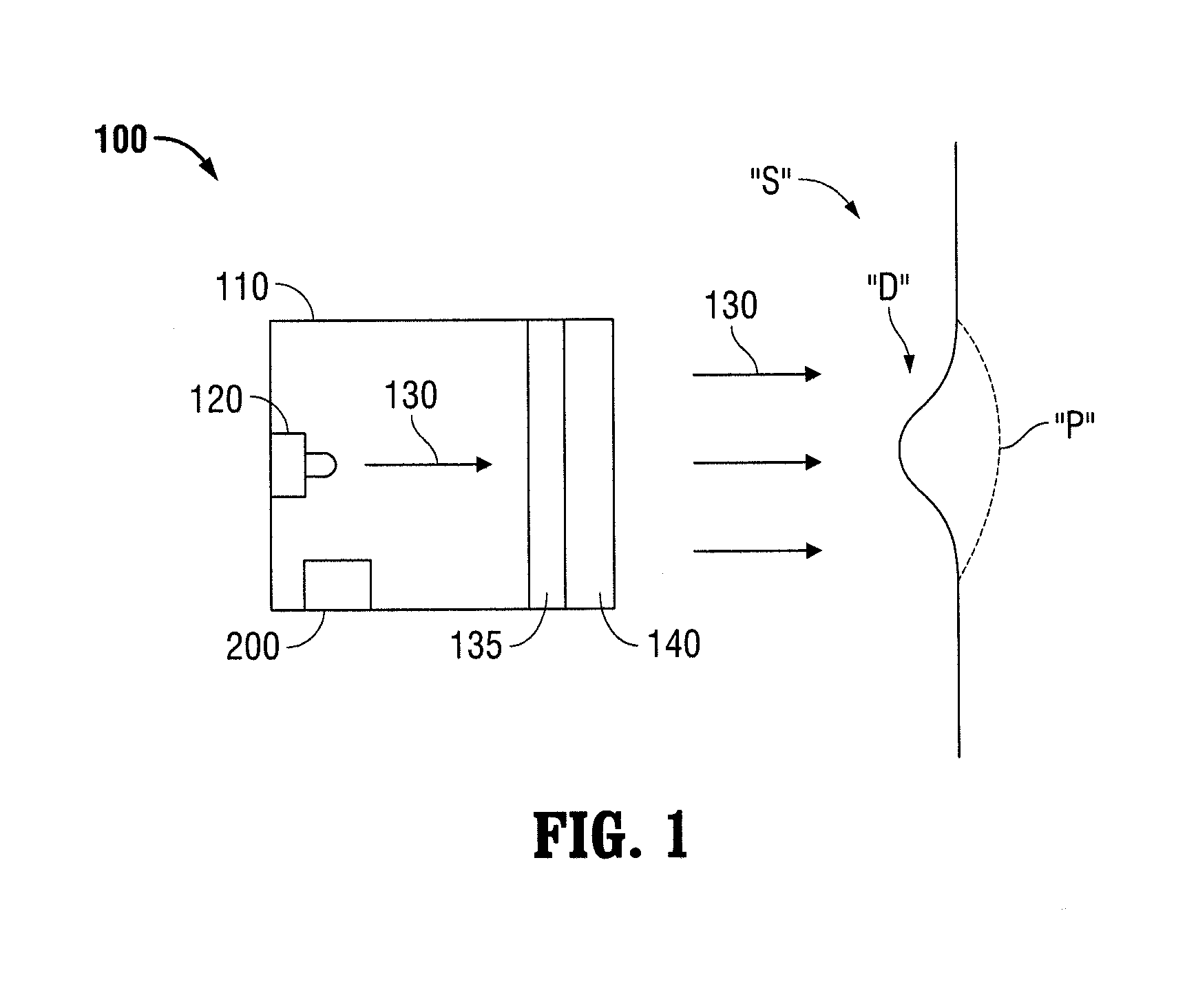
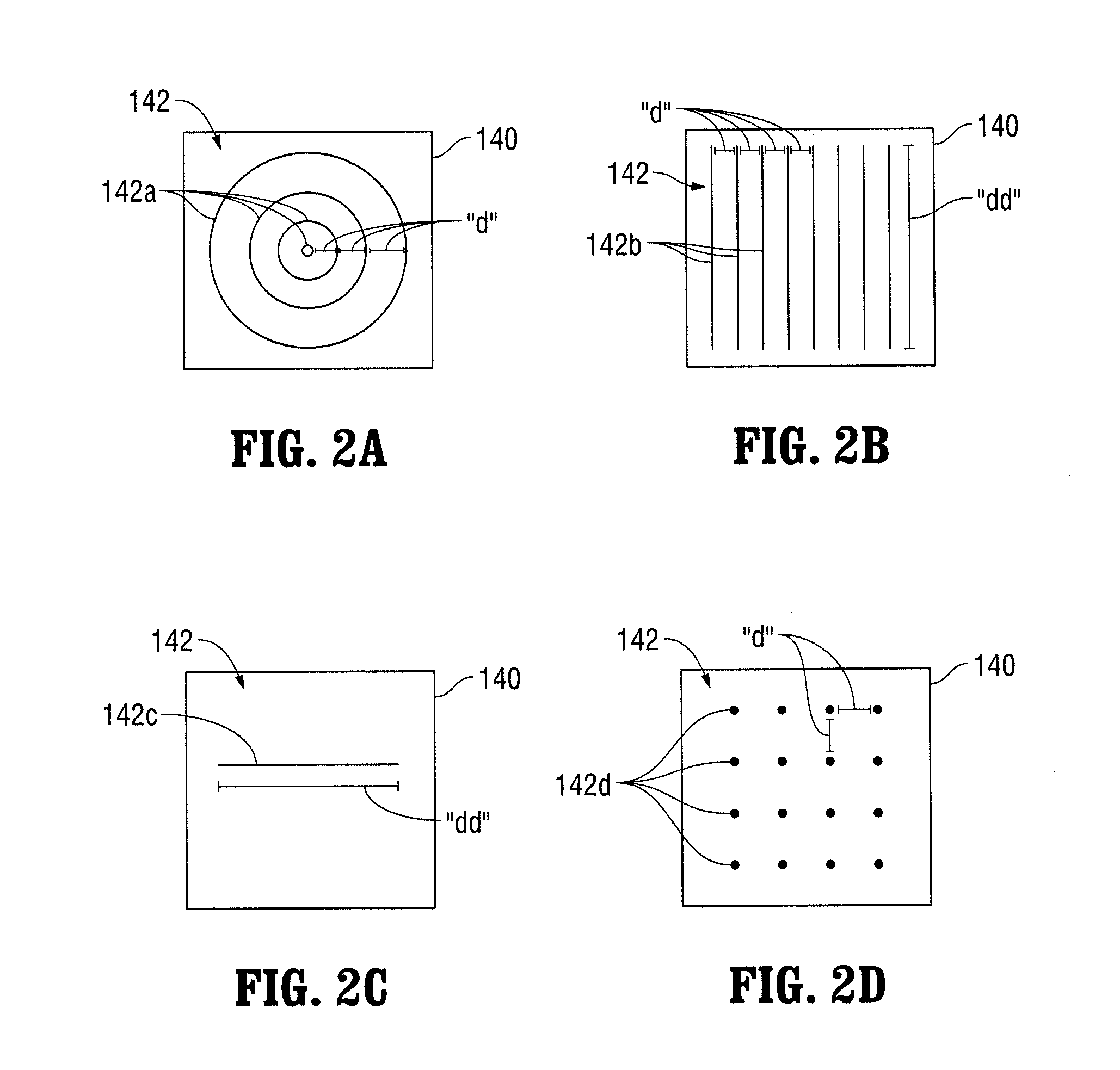
[0013]Another aspect of the present disclosure provides a method for measuring a desired portion of a surgical site including projecting light from a projector assembly into a surgical site and analyzing the projected light. The projector assembly may include a light source for projecting the light through a telecentric lens, and a mask operably coupled to the projector assembly. The light projected from the light source projects through the mask. The projected light through the mask may be a collimated pattern which does not significantly change in size as a function of a distance to a projected plane, i.e., the desired portion. The projected light may include multiple wavelengths of light, and the analyzing step may include measuring different features of tissue within the surgical site by comparing the different wavelengths of light. Additionally or alternatively, the mask may have a scale and the scale is projected onto the desired portion of the surgical site, and the analyzing step includes measuring the desired portion of the surgical site by comparing the desired portion with the projected scale. Additionally or alternatively, the mask may have concentric rings, each ring representing a radius of a given dimension, and the concentric rings are projected on a desired portion of the surgical site, and the analyzing step includes measuring the desired portion of the surgical site by comparing the desired portion with the concentric rings. The light source may have at least one lighting element and / or may include a diffuser for diffusing the light produced by the at least one lighting element. Additionally or alternatively, the mask may include a collimated pattern for projecting the collimated pattern onto the desired portion of the surgical site, and the analyzing step may include measuring the desired portion of the surgical site by comparing the desired portion with the collimated pattern. The pattern may correspond to a known or a series of known implant sizes corresponding to available mesh sizes. The telecentric lens and / or the mask may be formed of a flexible material. Additionally or alternatively, the method may further including positioning a polymetric scale external to the surgical site and projecting a scale through tissue for viewing within the surgical site. Thus, for example, the fixation points for a mesh may be projected from inside the abdomen through tissue to allow suturing or fixation from outside the abdomen.
[0014]Additionally or alternatively, another aspect of the present disclosure provides the method described above further including capturing an image of the projected light in the surgical site via an imaging unit. The imaging unit may be a CMOS camera and / or a raster scanning device. The method may further include performing parallax corrections of the captured image via a microprocessor operatively coupled to the imaging unit. The method may further include calculating measurement dimensions of the desired portion of the surgical site. The method may further include displaying the calculated measurement dimensions on a display operatively coupled to the microprocessor. The method may further include performing triangulation or distance sensing via a sensor. An interferometer may be operatively coupled to the sensor. The method may further include selecting an implant based on the measurement dimensions. Throughout this specification an implant may be a mesh, such as a hernia mesh, a non-woven device, a film, a tissue engineering scaffold and other types of implants. Where mesh is used as an example, other suitable implants may be substituted. Implants may be rapid prototyped using methods such as 3-D printing. For example, the method may further include transmitting the calculated measurement dimensions to a mesh printing device and creating a surgical mesh according to the measurements. The created mesh may include optimal fixation points.

Problems solved by technology

This is especially the case in minimally invasive surgery where access to the surgical site is limited.

Method used


Image

  • Telecentric Scale Projection System for Real-Time In-Situ Surgical Metrology
  • Telecentric Scale Projection System for Real-Time In-Situ Surgical Metrology
  • Telecentric Scale Projection System for Real-Time In-Situ Surgical Metrology

Examples


Embodiment Construction

[0023]Particular embodiments of the present disclosure are described hereinbelow with reference to the accompanying drawings; however, it is to be understood that the disclosed embodiments are merely exemplary of the disclosure and may be embodied in various forms. Well-known functions or constructions are not described in detail to avoid obscuring the present disclosure in unnecessary detail. Therefore, specific structural and functional details disclosed herein are not to be interpreted as limiting, but merely as a basis for the claims and as a representative basis for teaching one skilled in the art to variously employ the present disclosure in virtually any appropriately detailed structure.

[0024]Like reference numerals may refer to similar or identical elements throughout the description of the figures. As shown in the drawings and described throughout the following description, as is traditional when referring to relative positioning on a surgical instrument, the term “proximal...


PUM


Abstract

A system and method for determining endoscopic dimensional measurements including a projector assembly comprising a light source for projecting light through a telecentric lens and into a surgical site, and a mask coupled to the projector assembly. Light projected from the light source projects through the mask. The projected light through the mask may be a collimated pattern which does not significantly change in size as a function of the distance to a projected plane. The projected light patterns may include multiple wavelengths of light for measurements of different features of tissue and may be produced using a laser in conjunction with a light shaping optical diffuser, or using a light emitting diode in conjunction with a light shaping optical diffuser, or using a spatial filter. The projected light patterns may take the form of concentric rings with each ring representing a radius of a given dimension.

Description

CROSS-REFERENCE TO RELATED APPLICATIONS[0001]This application claims the benefit of and priority to U.S. Provisional Patent Application No. 61 / 675,397, filed Jul. 25, 2012, the entire disclosure of which is incorporated by reference herein.BACKGROUND[0002]1. Technical Field[0003]The present disclosure relates to a method and system for measuring a dimension of a desired portion of a surgical site. More particularly, the present disclosure relates to a method and system for projecting a pattern of a known size onto a desired portion of a surgical site for measuring the desired portion. The pattern may be used to select a suitably sized implant and show desired or optimal fixation points for an implant.[0004]2. Background of the Related Art[0005]Minimally invasive surgery, e.g., laparoscopic, endoscopic, and thoroscopic surgery, has many advantages over traditional open surgeries. In particular, minimally invasive surgery eliminates the need for a large incision, thereby reducing disc...

Claims


Application Information

Patent Timeline
Patent Type & Authority Applications(United States)
IPC IPC(8): A61B5/107
CPCA61B5/107G01B11/02G01B11/25G01B11/2513A61B5/6841A61B5/1075A61B90/06A61B2090/061B33Y80/00
Inventor PINTO, CANDIDO DIONISIODURVASULA, RAVIPOWER, JAMESMA, YONGPANDEY, ASHWINI KUMARTHOMAS, JONATHAN
Owner TYCO HEALTHCARE GRP LP
Learn More