
Liquid crystal display device with touch sensor, and electronic apparatus

a technology of touch sensor and display device, which is applied in the direction of instruments, computing, electric digital data processing, etc., can solve the problems of complex processing and achieve the effects of reducing costs, maintaining thinness and high performan

Active Publication Date: 2014-01-30
JAPAN DISPLAY INC
View PDF16 Cites 108 Cited by
  • Summary
  • Abstract
  • Description
  • Claims
  • Application Information

AI Technical Summary

Benefits of technology

This patent describes a liquid crystal display device with a touch sensor that includes a simplified electrode layer configuration. This simplification reduces the manufacturing process steps for the sensor pattern layer, resulting in cost reduction while maintaining thinness and high performance. The invention can be applied to various electronic apparatuses, such as mobile phones, televisions, digital cameras, and so on. Additionally, the patent describes the use of the liquid crystal display device with a touch sensor in electronic apparatuses such as on-vehicle equipment, where the display serves as a fuel meter, water temperature meter, speedometer, and the like.

Problems solved by technology

The liquid crystal display device with a touch sensor and the like typically have problems and requirements such as slimming down, space saving, simplification and reduction of manufacturing process and parts, that is, cost reduction by the simplification, and improvement in display quality and touch detection accuracy.
However, the manufacturing process of the liquid crystal display device with a touch sensor of sharing type requires a step for processing the sensor pattern and the like, so that the process is more complicated than that of the related liquid crystal display device with a touch sensor of non-sharing type and the like.

Method used


Image

  • Liquid crystal display device with touch sensor, and electronic apparatus
  • Liquid crystal display device with touch sensor, and electronic apparatus
  • Liquid crystal display device with touch sensor, and electronic apparatus

Examples


first embodiment

2. First Embodiment

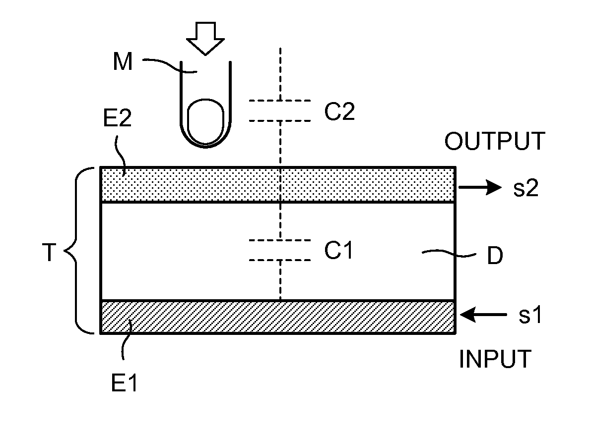
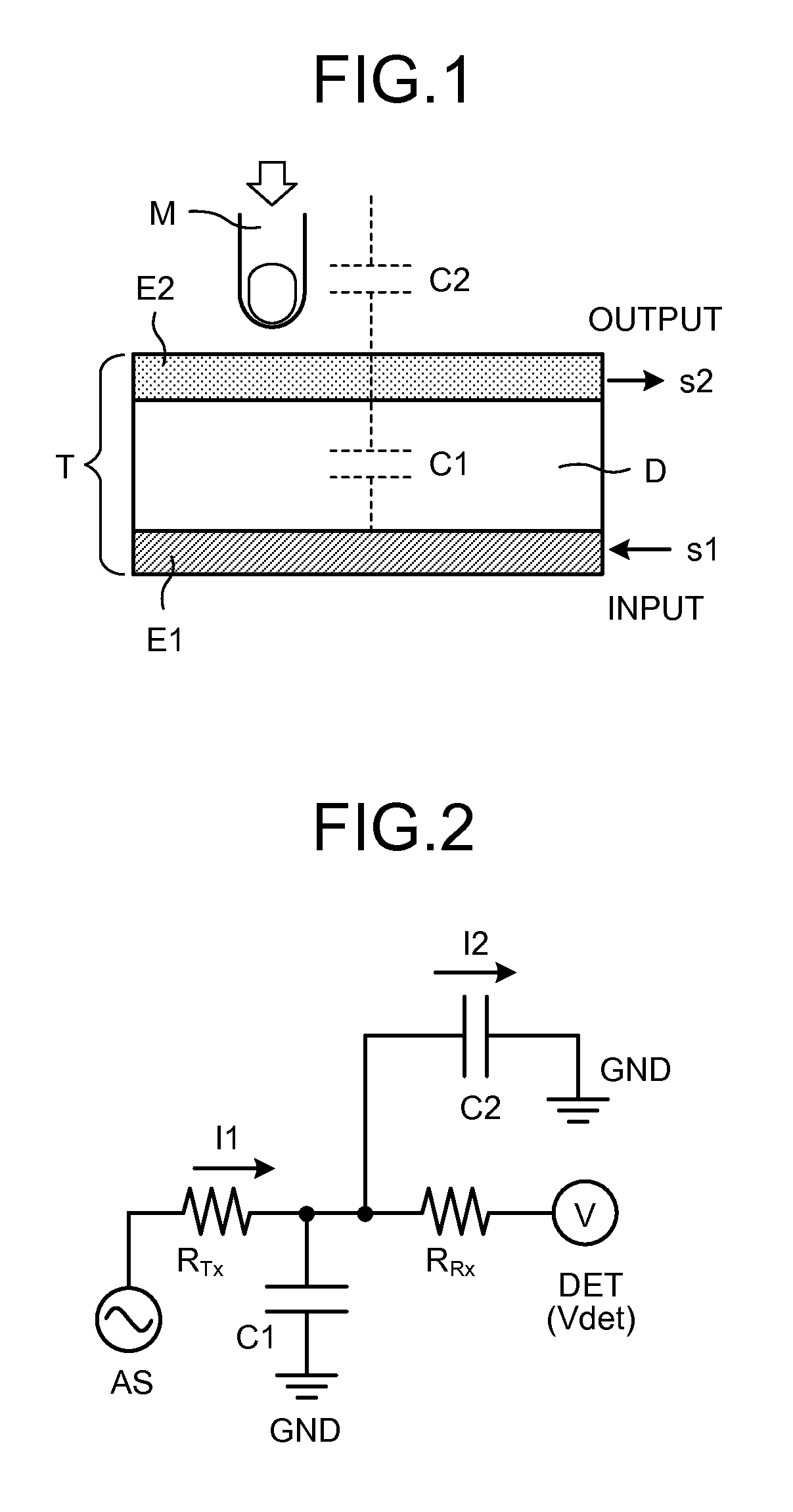
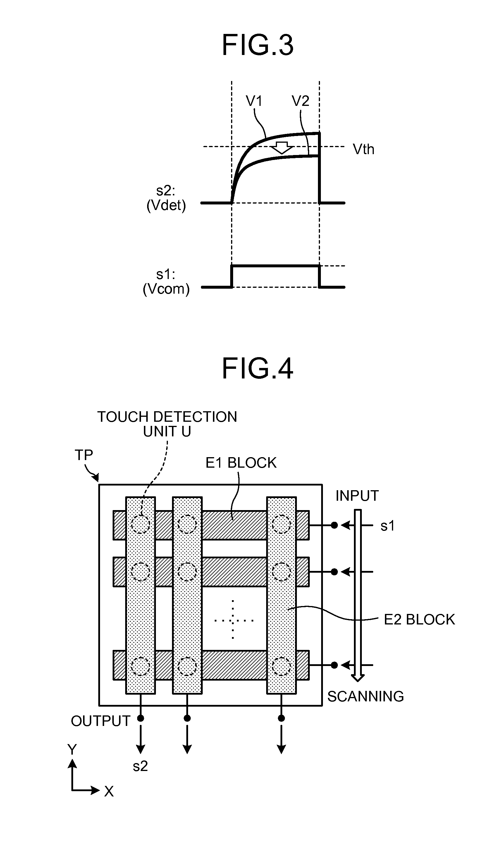
[0068]On the basis of the above description, a first embodiment will be described with reference to FIG. 9 and the like. In the configuration of the first embodiment, in contrast to the second comparative example (FIG. 8), the first common electrode section COM1 on the array substrate 10 is used as the transmitting electrode Tx, the second common electrode section COM2 at the inner side on the CF substrate 20 is used as the receiving electrode Rx, and the pattern layer of the receiving electrode Rx on the front surface of the CF substrate 20 is eliminated.

[0069]In the case of the panel section 920 of the liquid crystal display device with a touch sensor in the second comparative example (of the vertical electric field mode and the sharing type), with regard to the liquid crystal display function, wiring layers of the common electrode COM (the common electrode COM1 and the common electrode COM2) are provided to both the array substrate 10 and the CF substrate 20, w...

second embodiment

3. Second Embodiment

[0080]A second embodiment will be described with reference to FIG. 12 to FIG. 14, for example. In the first embodiment, a distance between the first electrode 51 serving as the transmitting electrode Tx and the second electrode 52 serving as the receiving electrode Rx is relatively short so that the capacitance formed therebetween may increase. Such an increase of the capacitance may have some effect on the sensibility of the touch detection. Accordingly, in the second embodiment, the pattern designs are devised as follows for the first electrode 51 and the second electrode 52.

[0081]3-1. Liquid Crystal Display Device with Touch Sensor (2)

[0082]FIG. 10 illustrates the schematic configuration of a main part of the panel section 1 of the liquid crystal display device with a touch sensor in the second embodiment. FIG. 10(a) is a diagram illustrating the X-Z cross section, and FIG. 10(b) is a diagram illustrating the Y-Z cross section. On the array substrate 10, provi...

third embodiment

4. Third Embodiment

[0100]Next, a third embodiment will be described with reference to FIG. 17 to FIG. 19. The third embodiment describes a configuration example of a liquid crystal touch panel module 100 including the panel section 1 of the liquid crystal display device with a touch sensor and a driver IC thereof or the like, and a configuration example of an electronic apparatus 500 including the liquid crystal touch panel module 100. Specifically, a drive system with respect to the floating pattern Rx2 in the second embodiment will be described as well.

[0101]4-1. Liquid Crystal Touch Panel Module, and Electronic Apparatus

[0102]FIG. 17 illustrates a functional block configuration example of the electronic apparatus 500 including the liquid crystal touch panel module 100 (liquid crystal display device with an in-cell capacitive touch sensor) in the third embodiment. Examples of the electronic apparatus 500 may include various devices having the liquid crystal display function and th...


PUM


Abstract

According to an aspect, a liquid crystal display device with a touch sensor has a liquid crystal display function and a touch sensor function. The liquid crystal device includes a first substrate including a pixel electrode and a first electrode; a second substrate including a second electrode; and a liquid crystal layer provided between the first substrate and the second substrate. When the liquid crystal display function is activated, the first and second electrodes are supplied with common voltage. When the touch sensor function is activated, the first electrode is applied with a first signal, and a second signal is detected through the second electrode.

Description

CROSS REFERENCES TO RELATED APPLICATIONS[0001]The present application claims priority to Japanese Priority Patent Application JP 2012-163421 filed in the Japan Patent Office on Jul. 24, 2012, and JP 2013-151009 filed in the Japan Patent Office on Jul. 19, 2013, the entire content of which is hereby incorporated by reference.BACKGROUND[0002]1. Technical Field[0003]The present disclosure relates to technologies used in a liquid crystal display device (LCD), a touch sensor (also referred to as a touch panel (TP)), a liquid crystal display device with a touch sensor (liquid crystal touch panel module), an electronic apparatus, and the like. Specifically, the present disclosure relates to technologies used in a liquid crystal display device with an in-cell capacitive touch sensor.[0004]2. Description of the Related Art[0005]As a liquid crystal display device with a touch sensor having a liquid crystal display function with a touch sensor function implemented, an in-cell touch panel confi...

Claims


Application Information

Patent Timeline
IPC IPC(8): G06F3/044
CPCG02F1/1333G02F1/1343G06F3/044G02F1/13338G06F3/0412G06F2203/04103G06F3/04166G06F3/0445G06F3/0446G06F3/0448G02F1/133302G02F1/134318G06F3/0416G09G3/3607G09G3/3648G09G2300/0426G09G2330/02G02F1/133345G02F1/133514G02F1/133707G02F1/134309G02F1/13439G02F1/136213G02F1/136286G02F1/1368G02F2201/121G02F2201/123
Inventor FURUTANI, NAOSUKEKURASAWA, HAYATOHAYASHI, MAKOTO
Owner JAPAN DISPLAY INC
Learn More