Method and apparatus for occupation detection
a technology for occupation detection and methods, applied in the field of location technologies, can solve the problems of increasing restrictions on the environment of occupation detection, affecting detection accuracy, and inevitably affecting signal strength, so as to improve the accuracy of detection results and reduce dependence on the environment
- Summary
- Abstract
- Description
- Claims
- Application Information
AI Technical Summary
Benefits of technology
Problems solved by technology
Method used
Image
Examples
embodiment 1
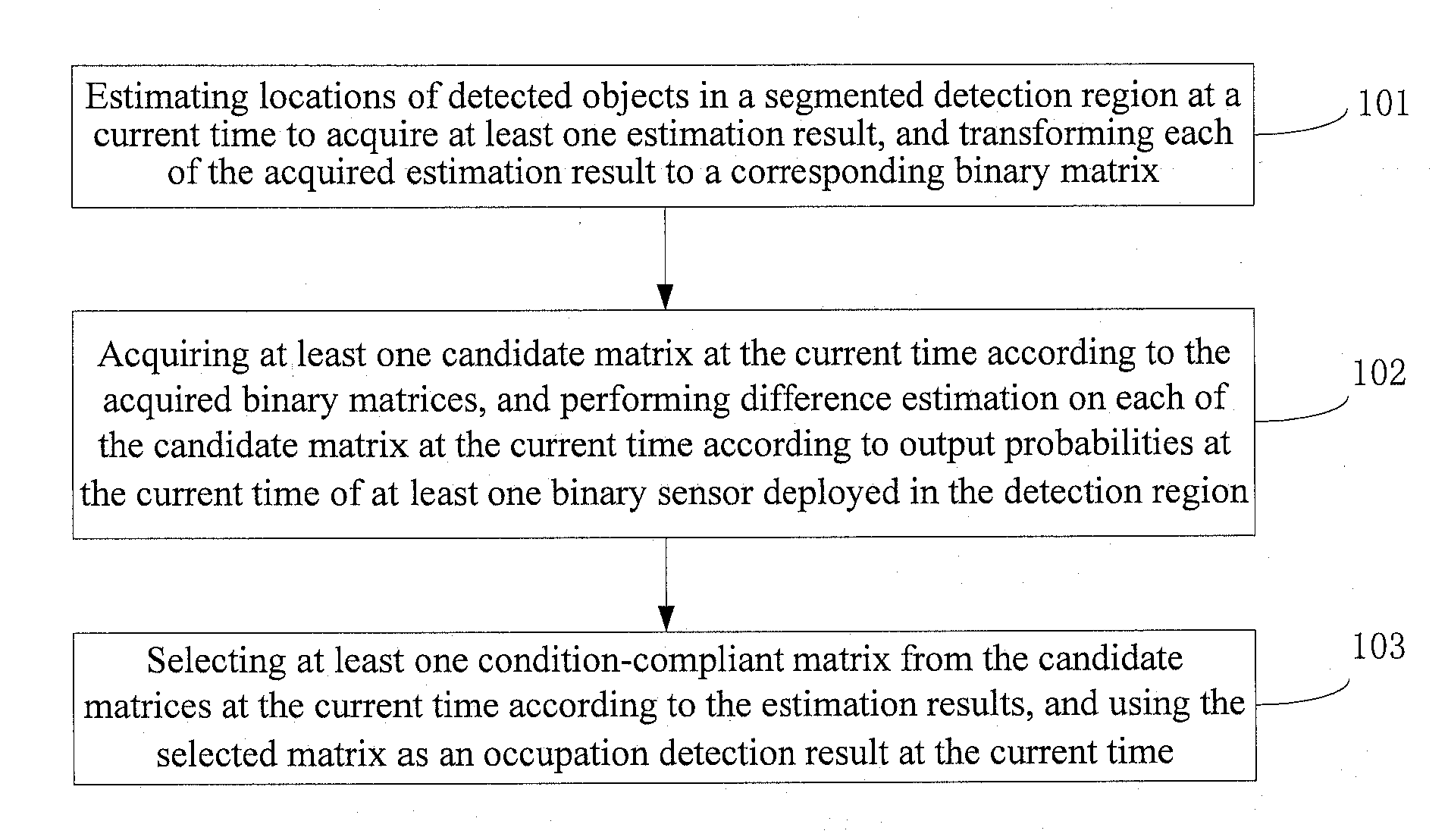
[0049]This embodiment provides a method for occupation detection. The method implements occupation detection by using a binary sensor, and further reduces restrictions caused by the environment to the occupation detection, and improves accuracy of the detection result. Referring to FIG. 1, the method provided in this embodiment includes the following steps:
[0050]101: estimating locations of detected objects in a segmented detection region at a current time to acquire at least one estimation result, and transforming each of the acquired estimation results to a corresponding binary matrix.
[0051]102: acquiring at least one candidate matrix at the current time according to the acquired binary matrices, and performing difference estimation on each of the candidate matrices at the current time according to output probabilities at the current time of at least one binary sensor deployed in the detection region.
[0052]The acquiring at least one candidate matrix at the current time according t...
embodiment 2
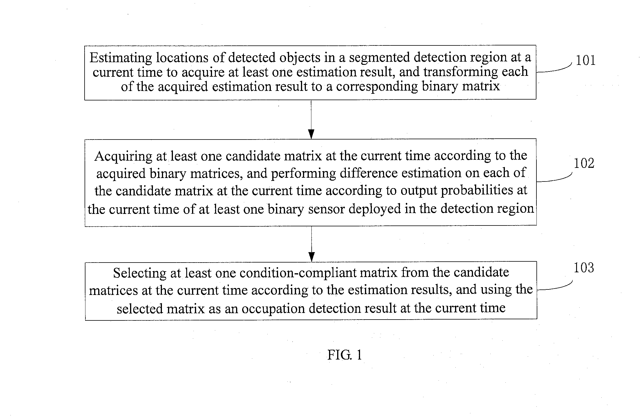
[0069]This embodiment provides a method for occupation detection. With reference to the content disclosed in Embodiment 1, for ease of description, this embodiment takes using a 2-norm as an estimation result of performing difference estimation on each of the candidate matrices at a current time as an example to describe the method for occupation detection. Referring to FIG. 2, the method provided in this embodiment includes the following steps:
[0070]201: estimating locations of detected objects in a segmented detection region at a current time to acquire at least one estimation result, and transforming each of the acquired estimation results to a corresponding binary matrix.
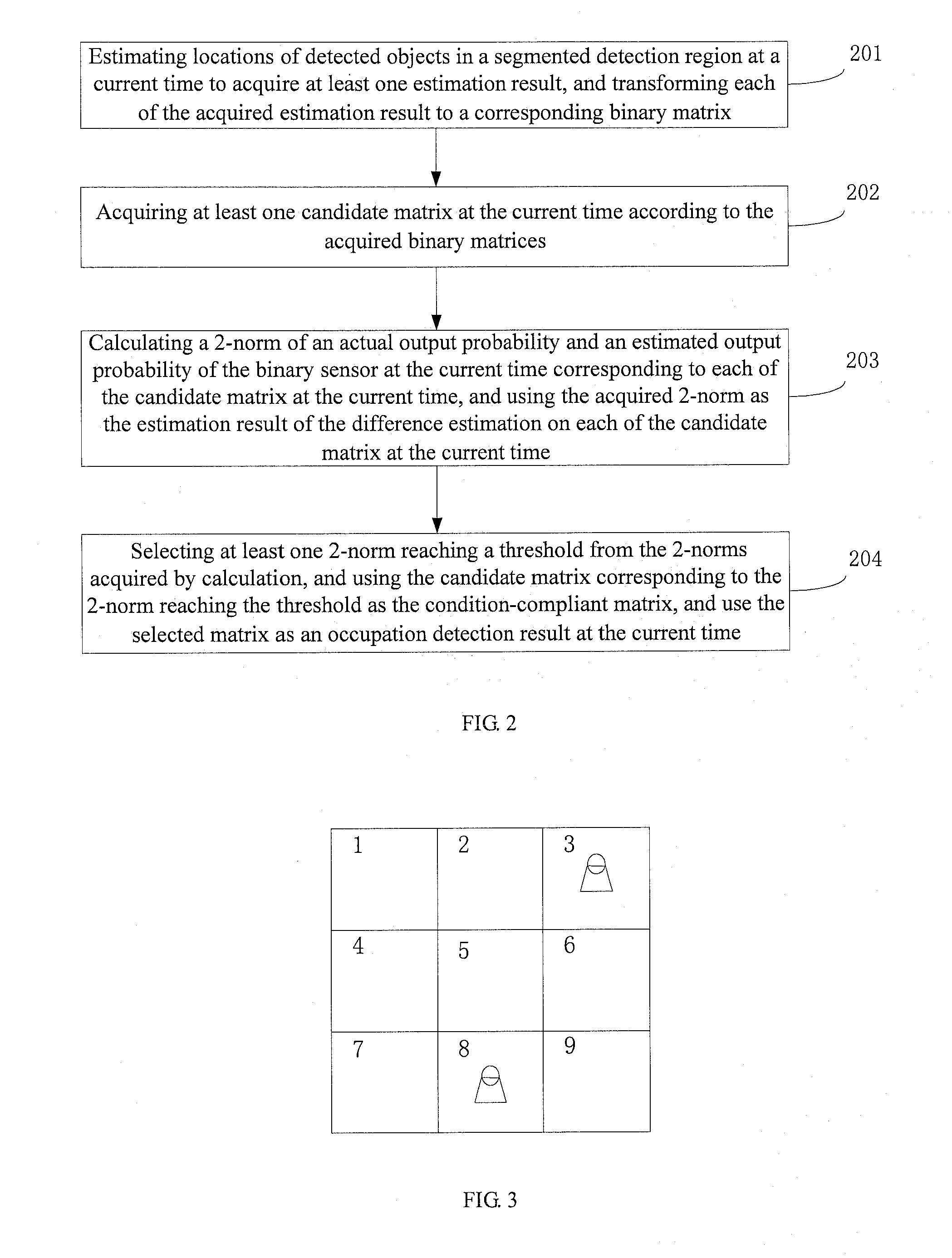
[0071]The size of the segmented detection region and the number of segmented detection regions are determined as required. In addition, in any of the segmented detection regions, any number of binary sensors can be deployed. This embodiment does not set limitations to the size of the segmented detection region, ...
embodiment 3
[0092]This embodiment provides a method for occupation detection. With reference to the content disclosed in Embodiment 1, for ease of description, this embodiment takes using a sum of a 2-norm and a Hamming distance as an estimation result of performing difference estimation on each of the candidate matrices at a current time as an example to describe the method for occupation detection. Referring to FIG. 7, the method provided in this embodiment includes the following steps:
[0093]701: estimating locations of detected objects in a segmented detection region at a current time to acquire at least one estimation result, and transforming each of the acquired estimation results to a corresponding binary matrix.
[0094]This step may be implemented using the same manner as step 201 in Embodiment 2. For details, reference may be made to the description in step 201 in Embodiment 2, which is not detailed herein any further.
[0095]702: acquiring at least one candidate matrix at the current time ...
PUM
 Abstract
Description
Claims
Application Information
 - R&D
- Intellectual Property
- Life Sciences
- Materials
- Tech Scout
- Unparalleled Data Quality
- Higher Quality Content
- 60% Fewer Hallucinations
Browse by: Latest US Patents, China's latest patents, Technical Efficacy Thesaurus, Application Domain, Technology Topic, Popular Technical Reports.
© 2025 PatSnap. All rights reserved.Legal|Privacy policy|Modern Slavery Act Transparency Statement|Sitemap|About US| Contact US: help@patsnap.com


