
Fracture Water Treatment Method and System

a treatment method and water treatment technology, applied in the direction of machines/engines, well accessories, sedimentation settling tanks, etc., can solve the problems of uneconomical extraction of hydrocarbon molecule compounds contained therein, the cost of production is well above the market price of similar products, and the situation is uneconomical

Inactive Publication Date: 2014-01-30
MBJ WATER PARTNERS
View PDF6 Cites 41 Cited by
  • Summary
  • Abstract
  • Description
  • Claims
  • Application Information

AI Technical Summary

Benefits of technology

The present invention has the advantage of reducing the need for disposal of brine water and chemical biocides in fracturing operations. The invention achieves this by coalescing and converting dissolved salts into suspended particles that are separated and incorporated with recovered proppant and fines for reuse in subsequent fracturing operations. The invention also eliminates the need for sludge or other solid waste disposal facilities and prevents the formation of scale encrustations. Additionally, the invention is able to generate a positive charge in the water, which is believed to reduce the presence of flow-reducing structures in the formation. The size of suspended solids is also reduced, making it easier to pass the water through devices for generating positive charge in the water.

Problems solved by technology

At the same time, the Industry also discovered the existence of large quantities of heavy and light hydrocarbon compound mixtures that were nonconventional in structure and were so enmeshed in the complex material matrixes that the hydrocarbon molecule compounds contained therein could not be extracted economically.
Although the shale oil proved to be a very suitable hydrocarbon product, its cost of production was well in excess of the market price of similar products; thus this situation proved to be uneconomical.
Additional development and investment was not justified at that time.
However some oil companies were concerned about the dangers in using explosives as a means of extending the productive life of depleting oil fields; and, in the late nineteen forties, the practice of using highly-pressured water and sand mixtures to produce fissures or fractures in the pay-zone areas began.
However, during the period when the application of hydraulic fracturing was becoming more wide spread, its growth, technologically and operationally, was carried out in a very haphazard, hit and miss, ad hoc manner.
Many of the improvements that were made were the result of unscientifically developed trial and error attempts to improve the rate of production in an oil well as well as trying to extend the economic life of established oil fields.
The best example of this unscientific approach, in trying to solve specific processing problems, is what was occurring in the proper selection and use of various types of proppants in the hydraulic fracturing process.
Without the proper proppants that are strong enough and correctly sized to keep the fissures continuously open, the well's production rate will decline rapidly as proppant fines and softer material particles fill up the fissures.
These will decrease the rate of flow and ultimately block the flow of hydrocarbons into the well bore.
The key issue here is that the proper proppant that should be used in a hydraulic fracturing process is the single most important factor that is needed in achieving and maintaining the proper “voids ratio” that is needed in the pressurized water fractured channels to be able to realize the full benefit of the hydraulic fracturing process.
With the introduction of steerable vertical and horizontal drilling equipment together with very high pressure fracturing pumps (called by some “intensifiers”), the oil industry then applied the same hydraulic fracturing techniques that had been successfully developed and used in vertical oil well hydraulic fracturing operations and applied these same procedures to the well bores that were horizontally drilled in the deep shale formations but with less than satisfactory results.
It was not until the industry started to realize that the traditional principles of petroleum technology were not fully applicable to the newly developed attempts to extract entrapped liquid and gaseous hydrocarbons from mineral rock formations that did allow them to flow freely even in deep high temperature and high pressure locations.
A smaller size proppant would not be as effective and this would result in a significant reduction in the amount of hydrocarbon product that could be produced.
There is great concern such toxic chemical-bearing fracturing water could migrate into a potable water aquifer.
Detergent soap mixtures as well as chemicals such as potassium chloride are commonly used as surface-tension-reducing surfactants and could create public health issues.
Much of the proppant remains behind in these channels; however, a significant amount comes out in the back-flow water.
Treatment and / or disposal of this flow-back are significant issues for the industry.
Ohio quakes put pressure on use of fracturing.
Another significant micro-organism type problem is the possible presence of a strain of microbes that have an affinity for seeking out and digesting any free sulfur or sulfur bearing compounds and producing hydrogen sulfides that must be removed from any product gas stream because it is a highly dangerous and carcinogenic material.
In addition to the possibility of micro-organisms multiplying and blocking the flow of hydrocarbon product, the presence of dissolved solids in the water solution can also be a problem in the injected water mixture.
In order to avoid this condition, attempts are made in current industry practice to have the dissolved solids coalesce and attach themselves to the suspended or other colloidal particles present in the water mixture to be removed before injection in the well; however, those efforts are only partly effective.
The use of ultra violet light in conjunction with reduced amounts of chemical biocide has proven to be only partially effective in killing water borne micro-organisms.
Both these systems, however, lack the intensity and strength to effectively kill all of the water-borne micro-organisms with only one weak short time residence exposure and with virtually no residual effectiveness.
Also, some companies use low-frequency or low-strength electro-magnetic wave generators as biocide / coalescers; however, these too have proven to be only marginally effective.
In some examples, the injecting of the particulate is decreased when the slagging material viscosity is so low that the flow rate through the kiln is too fast for fusing of proppant material.

Method used


Image

  • Fracture Water Treatment Method and System
  • Fracture Water Treatment Method and System
  • Fracture Water Treatment Method and System

Examples


Embodiment Construction

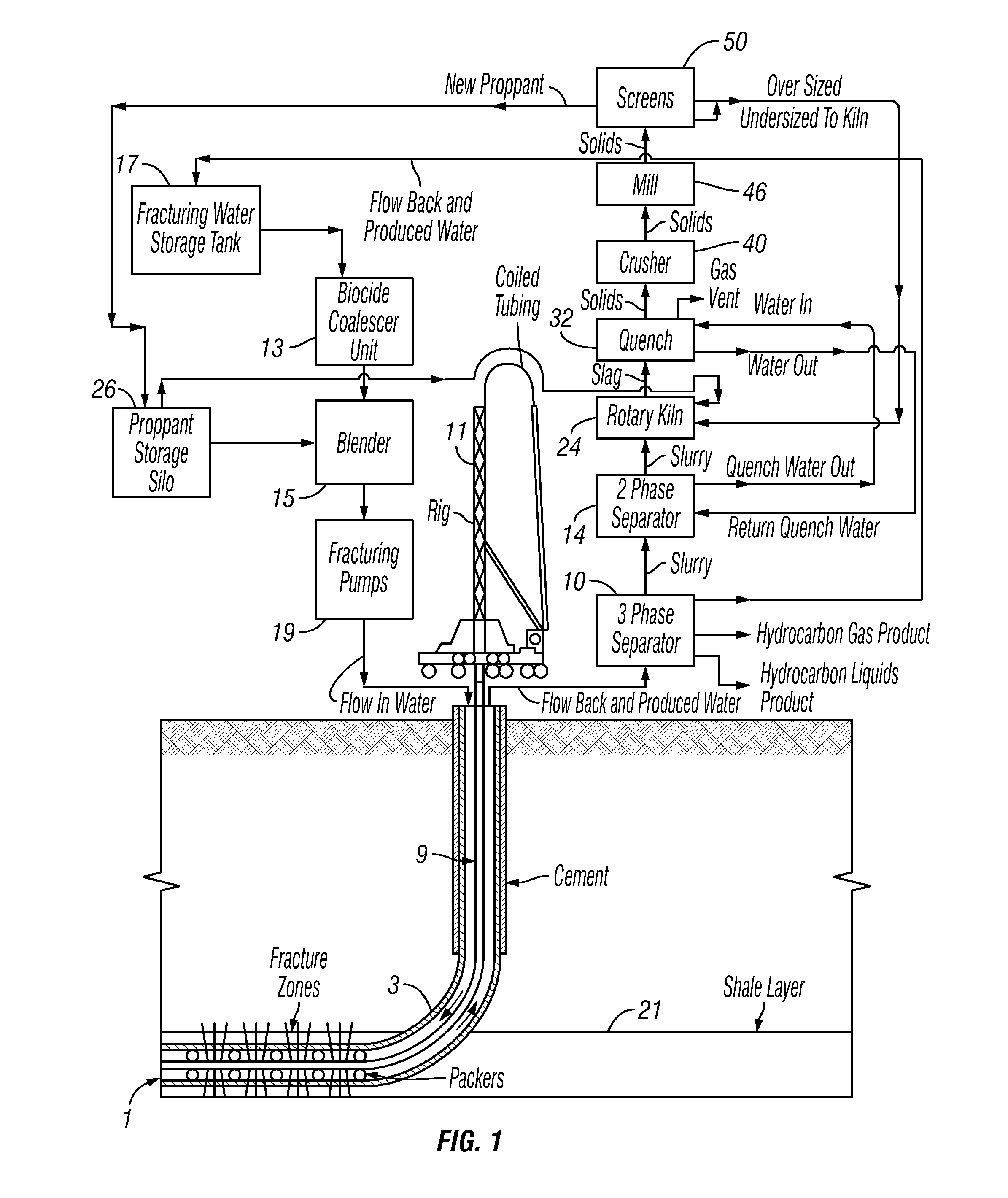
[0110]Referring now to FIG. 1, a flow diagram of the use of the invention in a hydrocarbon well having a well bore 1 with cemented casing 3 passing through fracture zones that are isolated by packers. Coil tubing 9 is inserted by rig 11 for fracture operations known to those of skill in the art.

[0111]Flow back (and / or produced) water is routed to three-phase solids / liquids / gas / hydrocarbon / water separator 10, from which any hydrocarbon liquids and gases are produced, and water from separator 10 is routed to a fracturing-water storage tank 17 which may also include water from another source (aka “make up” water). Wet solids are passed from three-phase separator 10 to two-phase separator 14, which produces water that is passed to a quench system 32 and slurry that are passed to kiln 24. Slag is passed from kiln 24 through quench system 32 to crusher 40 and then to mill 46. Milled material is separated into a specified size at screen 50 that is sent to a proppant storage silo 26, which ...


PUM

PropertyMeasurementUnit
Lengthaaaaaaaaaa
Lengthaaaaaaaaaa
Frequencyaaaaaaaaaa

Abstract

A method and system for treatment of flow-back and produced water from a hydrocarbon well in which fracturing operations are carried out using a phase separation and creating of positive charge in the water.

Description

CROSS-REFERENCE TO RELATED APPLICATIONS[0001]This application is a continuation in part of U.S. application Ser. No. 13 / 594,497 filed Aug. 24, 2012, which claims priority to U.S. Provisional App. No. 61 / 676,628, filed Jul. 27, 2012. This application also claims priority to U.S. Divisional application Ser. No. 13 / 753,310, filed on Jan. 29, 2013.BACKGROUND OF THE INVENTION[0002]This invention concerns the apparatus and processing steps for treating the flow-back and produced water and the other constituents that are used to hydraulically cause the creation of channels or fractures or fissures in hydrocarbon wells (for example, deep oil-shale deposits).[0003]Over the centuries, people have tried different ways to take advantage of and use the inherent qualities of naturally-occurring hydrocarbon compounds to enhance his life style and cope with the many challenges of existence. For over two thousand years, the “Burning Sands” of Kirkuk, in Iraq, provided heat to Kurdish tribes, which c...

Claims


Application Information

Patent Timeline
IPC IPC(8): C02F1/00B01D21/34B01D19/00
CPCC02F1/008B01D19/0063B01D21/34B01D19/00E21B43/267E21B21/065B01D17/0208B01D21/10E21B43/2607E21B43/35C02F1/487C02F1/484C02F2103/06C02F2201/483B01D17/12B01D21/24B01D21/2494C02F2103/10B01D17/0214B01D17/04B01D19/0068C02F2101/32C02F2209/42B01D21/0009C02F2209/005C02F2209/02
Inventor MUNISTERI, JOSEPH G.
Owner MBJ WATER PARTNERS
Learn More