Aircraft fuel cell system

a fuel cell and aircraft technology, applied in the field of aircraft systems, to achieve the effect of improving the ability to manage heat generated

Inactive Publication Date: 2014-01-23
GENERAL ELECTRIC CO
View PDF9 Cites 9 Cited by
  • Summary
  • Abstract
  • Description
  • Claims
  • Application Information

AI Technical Summary

Benefits of technology

[0004]Accordingly, it would be desirable to have aircraft systems using fuel cells with improved capability to manage heat generated during fuel cell operation.

Problems solved by technology

They operate at higher temperatures, and managing such heat generation can be a challenge in an aircraft system environment.

Method used


Image

  • Aircraft fuel cell system
  • Aircraft fuel cell system
  • Aircraft fuel cell system

Examples


Embodiment Construction

[0010]Referring to the drawings herein, identical reference numerals denote the same elements throughout the various views.

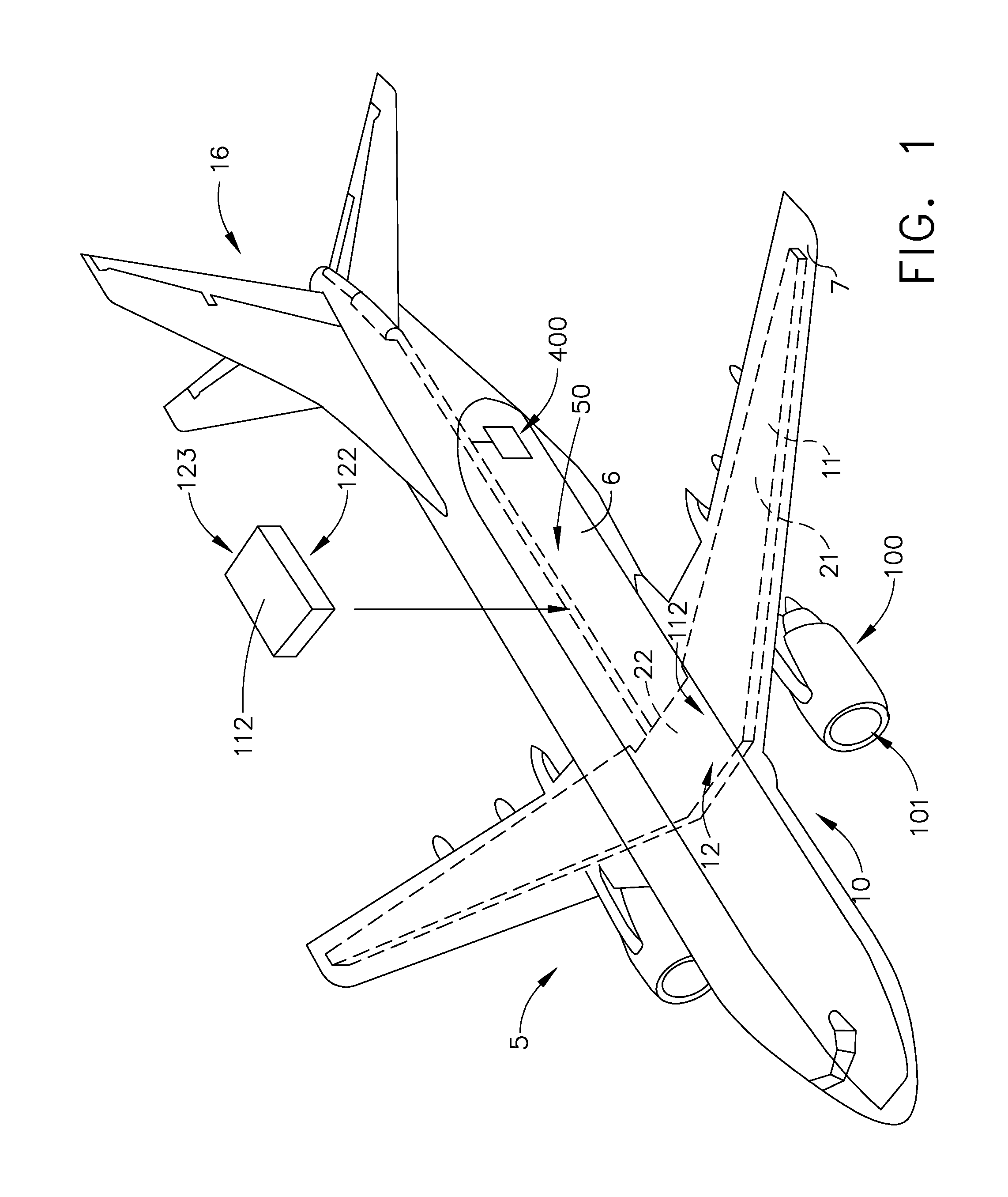
[0011]FIG. 1 shows an aircraft system 5 according to an embodiment of the present invention. The exemplary aircraft system 5 has a fuselage 6 and wings 7 attached to the fuselage. The aircraft system 5 has a propulsion system 100 that produces the propulsive thrust required to propel the aircraft system in flight. Although the propulsion system 100 is shown attached to the wing 7 in FIG. 1, in other embodiments it may be coupled to other parts of the aircraft system 5, such as, for example, the tail portion 16.

[0012]The exemplary aircraft system 5 has a fuel storage system 10 for storing one or more types of fuels that are used in the propulsion system 100. The exemplary aircraft system 5 shown in FIG. 1 uses two types of fuels, as explained further below herein. Accordingly, the exemplary aircraft system 5 comprises a first fuel tank 21 capable of storing a fir...


PUM

PropertyMeasurementUnit
temperatureaaaaaaaaaa
operating temperatureaaaaaaaaaa

Abstract

An aircraft system comprising a fuel storage system comprising a first fuel tank capable of storing a first fuel and a second fuel tank capable of storing a second fuel is disclosed herein. The aircraft system further comprises a fuel cell system comprising a fuel cell capable of producing electrical power using at least one of the first fuel or the second fuel, and a fuel delivery system capable of delivering a fuel from the fuel storage system to the fuel cell system.

Description

CROSS-REFERENCE TO RELATED APPLICATION[0001]This is a national stage application under 35 U.S.C. § 371(c) prior-filed, co-pending PCT patent application serial number PCT / U.S. 11 / 54403, filed on Sep. 30, 2011, which claims priority to U.S. provisional application serial number 61 / 388441, filed Sep. 30, 2010, the entire contents of which are incorporated herein by reference.BACKGROUND OF THE INVENTION[0002]The technology described herein relates generally to aircraft systems, and more specifically to aircraft fuel cell systems.[0003]Fuel cells are electrochemical devices that convert a supplied fuel into electricity. It generates electricity inside a cell through reactions between the fuel and an oxidant, triggered in the presence of an electrolyte. Fuel cells are characterized by their electrolyte material. A solid oxide fuel cell (“SOFC”) is an electrochemical conversion device that produces electricity directly from oxidizing a fuel. The SOFC has a solid oxide or ceramic, electrol...

Claims


Application Information

Patent Timeline
Patent Type & Authority Applications(United States)
IPC IPC(8): H01M8/04
CPCH01M8/04201B64D37/30B64D2041/005F17C2221/033F17C2223/0161F17C2223/033F17C2270/0189Y02T90/40Y02E60/50
Inventor EPSTEIN, MICHAEL JAYVONDRELL, RANDY M.WEISGERBER, ROBERT HAROLDKARVOUNTZI, GEORGIA C.
Owner GENERAL ELECTRIC CO
Why Eureka
Try Eureka