
Compressable catheter tip with image-based force sensing

a compression catheter and force sensing technology, applied in the field of catheters, can solve the problems of high probability, long rfa procedure, and inability to stop the arrhythmias of the procedure,

Active Publication Date: 2014-01-16
SIEMENS HEALTHCARE GMBH
View PDF8 Cites 13 Cited by
  • Summary
  • Abstract
  • Description
  • Claims
  • Application Information

AI Technical Summary

Benefits of technology

The present invention provides several benefits including the advantage of not needing additional sensors or wires, the contact force remains uniform as the catheter and patient anatomy move, and there is a buffer to decrease contact force if there is excessive movement that could harm the patient. The invention can also be used in systems that use fiber-optic or other force sensors as a back-up or secondary measure, especially for systems that have a high risk of excessive force.

Problems solved by technology

If lesions of sufficient depth and area are not being formed, because of insufficient contact and / or power, the RFA procedure will tend to be much longer and there will be a higher probability that the procedure will not be successful in stopping the arrhythmias, such that a follow-up procedure will be needed.
Conversely, if there is too much force and / or too much power there are potential risks including penetration of the tissue wall, esophageal injury, cardiac tamponade or perforations from steam pops (particularly during irrigated ablation procedures at high power) (this is noted in further detail in a presentation by Y. Yang, entitled “Atrial Fibrillation Ablation, The emerging role of stereotaxis”, University of California Davis Medical Center, Department of Internal Medicine, Division of Cardiovascular Medicine, 2011, http: / / wvvw.ucdmc.ucdavis.edu / internalmedicine / cardio / pdf / atrial%20fibrillation%20ablation%202011.pdf).
While image guidance systems and techniques can provide visualization of the catheter tip, and sometimes localization of the tip within some coordinate space, the challenge is often in relating that tip information to the actual location of the anatomy of interest.
Sometimes this might be accomplished by using optimal imaging planes that clearly show both the anatomy and the device, although this can be difficult in a complex anatomy such as the heart.
In the case of the heart, this is further complicated by the heart beating motion, patient breathing motion and catheter motion.
Other techniques involve the use of pre-acquired volumetric imaging data or 3D models of the anatomy superimposed with the real-time imaging, but these may also have inaccuracies due to registration errors stemming from the local motions, as well as from more global patient shifts.
Thus, using imaging techniques alone, it can be very difficult to definitively judge whether an ablation tip is in good or appropriate contact with the tissue surface or not.
While the user has some feel of the resistance as the catheter is navigated towards the target anatomy, once at the target there usually isn't enough sensitivity for the user to tell how good the contact is between the ablation tip and the tissue surface.
While using magnetics to control the catheter movement, this system is not MRI-compatible and instead is usually integrated with a fluoroscopy system.
While a force-sensing tip would offer clinical benefits, the addition of that capability in an MRI-compatible catheter would further complicate the design.

Method used


Image

  • Compressable catheter tip with image-based force sensing
  • Compressable catheter tip with image-based force sensing
  • Compressable catheter tip with image-based force sensing

Examples


Embodiment Construction

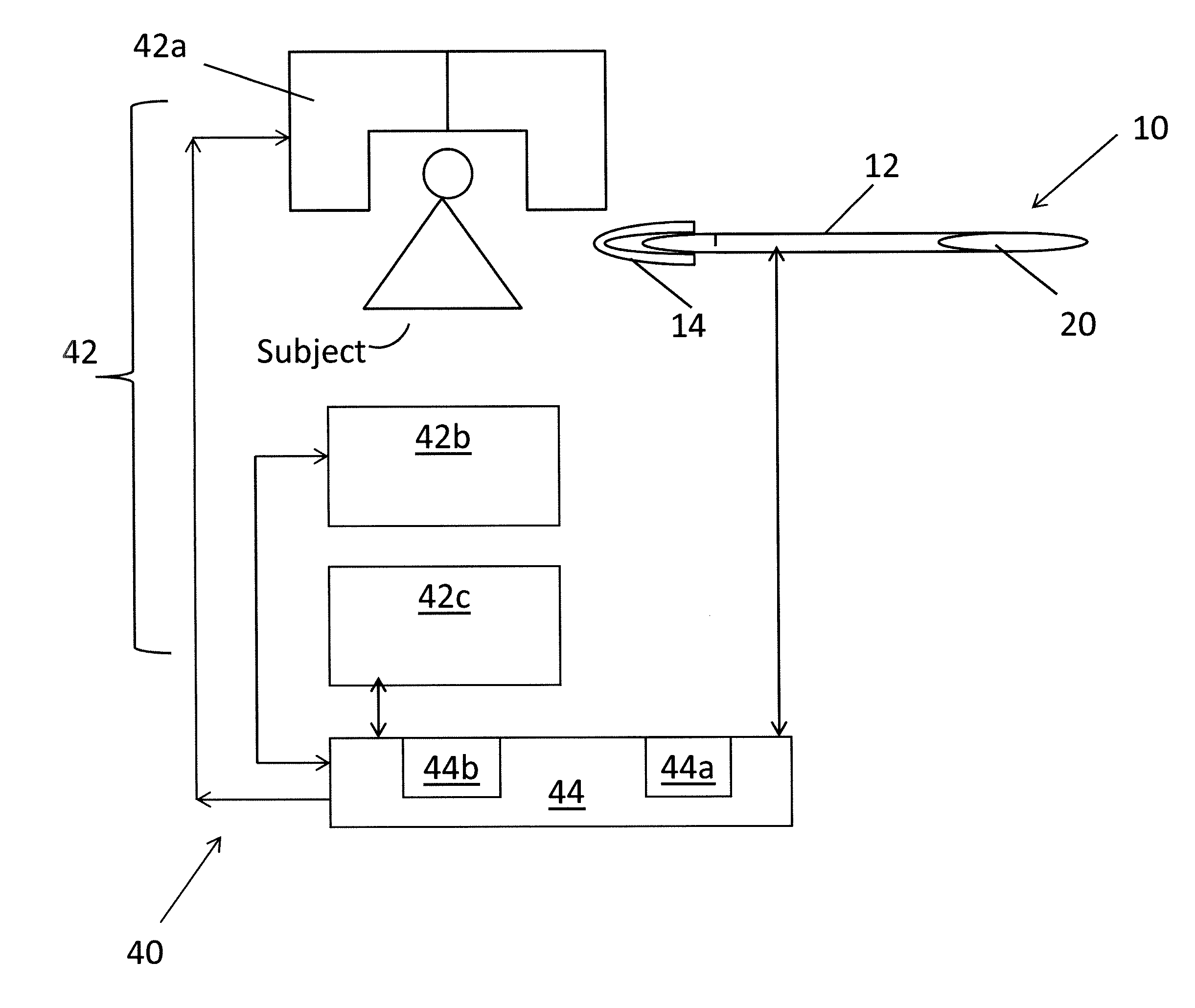
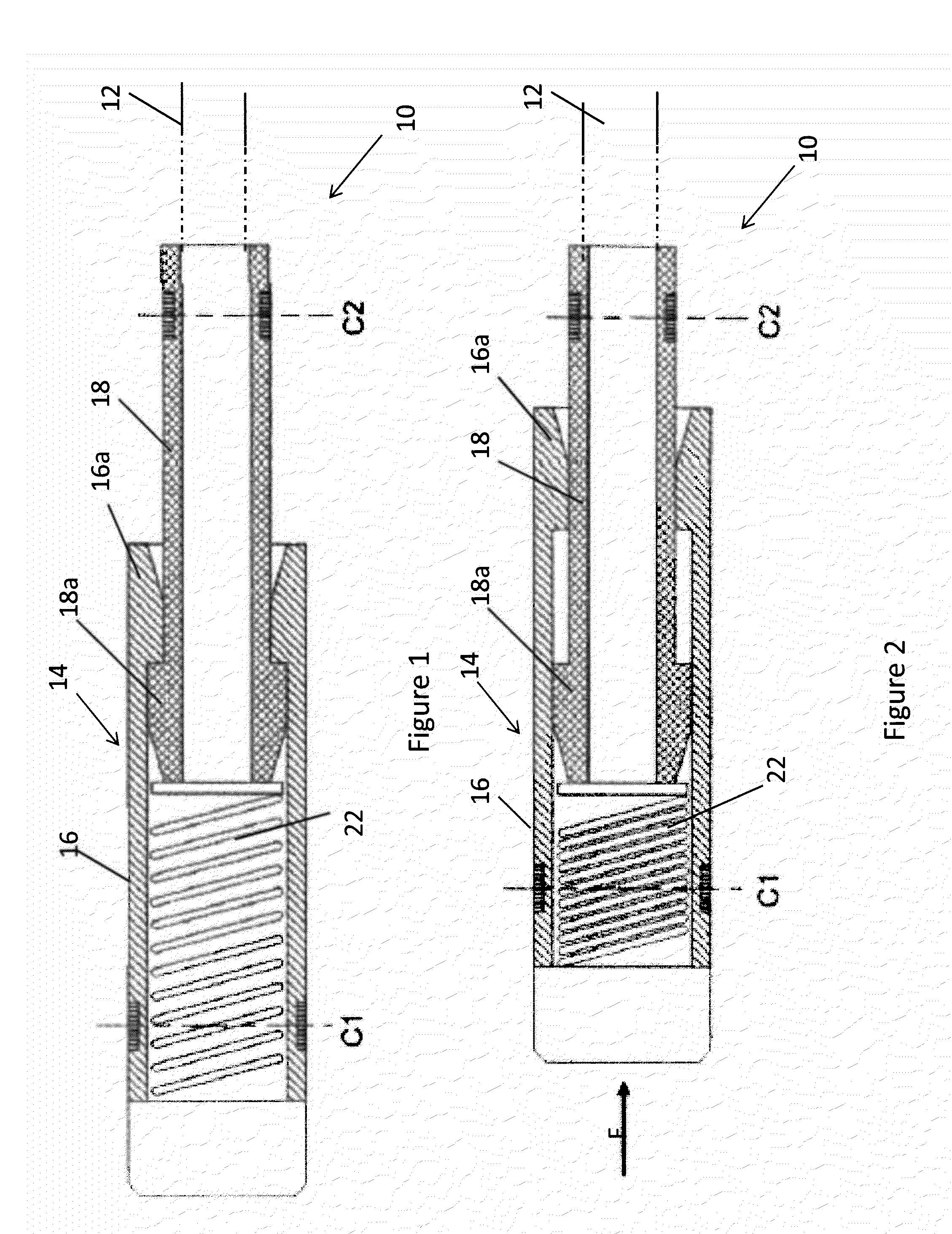
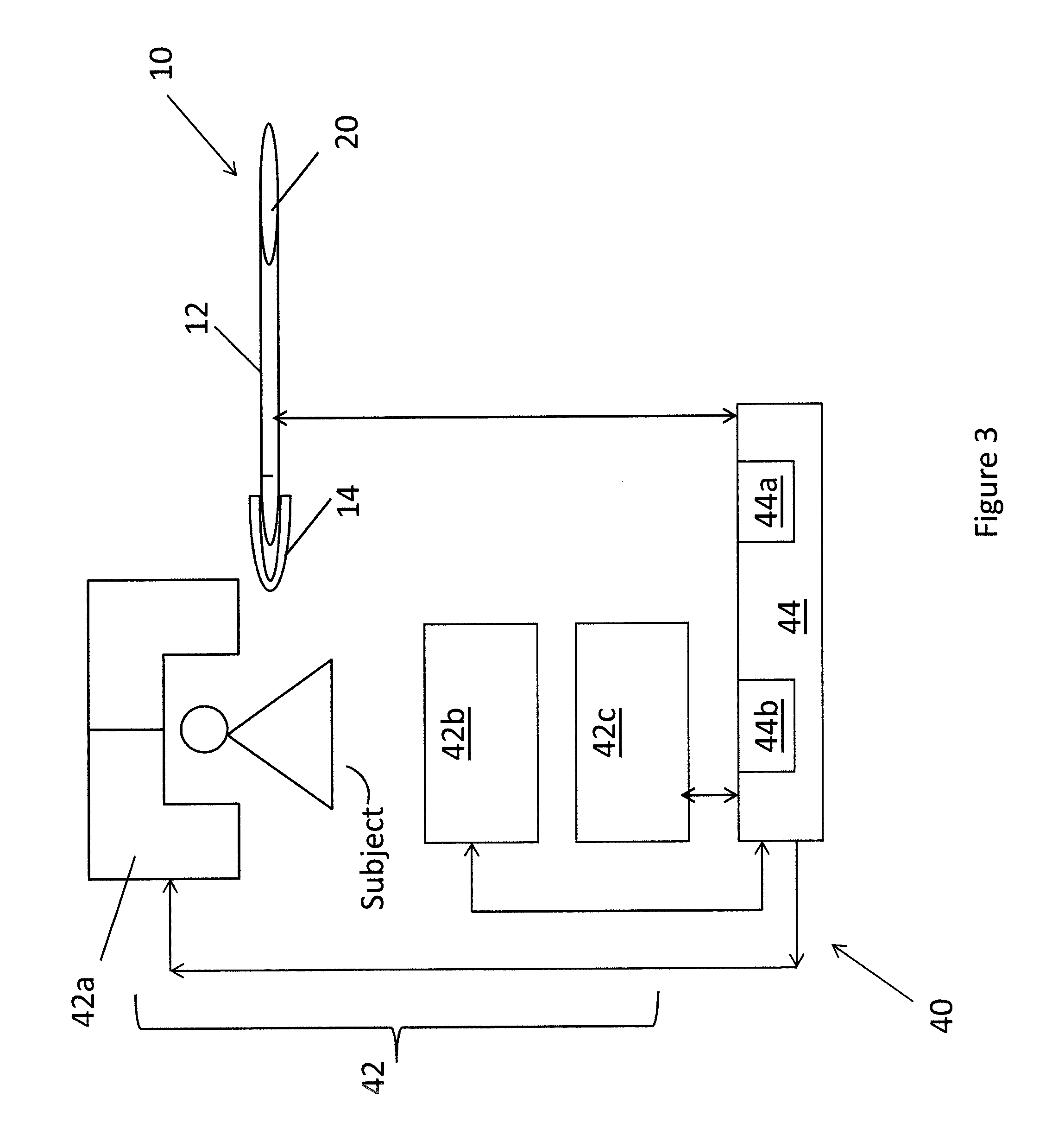
[0027]FIG. 1 is an illustration of a catheter 10 comprising a catheter shaft 12 that is formed as a flexible hollow tube. The shaft 12 may be constructed, for example, of a flexible polymer tubing (such as the Pebax brand) or any other material that may be used for medical applications. The catheter 10 also comprises a compressible catheter tip 14 that is attached to the end of the shaft 12 to be inserted in a patient's body. The tip 14 has two main sections, a rigid distal tip section 16 which includes, for example, an ablation tip and a rigid proximal tip section 18 which is fixed to the catheter shaft 12. The two sections 16, 18 generally follow the form of the shaft 12 and are generally tubular. Further, the two sections 16, 18 are configured and dimensioned so that the distal tip section 16 is interlocked with the proximal tip section 18 and the distal tip section 16 is adapted to freely slide back and forth over the proximal tip section 18, within certain limits. The proximal ...


PUM


Abstract

A catheter (10) comprising a catheter tip (14) that is adapted to have deflection of an associated spring (22) detected by imaging techniques and to have that deflection be translated into an estimation of the tip (14) contact force.

Description

FIELD OF THE INVENTION[0001]This invention generally relates to catheters and, more particularly to, catheters used for ablation procedures.BACKGROUND OF THE INVENTION[0002]Catheters are medical devices in the form of hollow flexible tubes for insertion into a part of the body usually to permit the passage of fluids or keep open a passageway. A catheter is normally accompanied with accessory components such as a control handle, catheter tips, surgical tools, etc., depending upon the application (and thus as a whole may be referred to, more properly, as a catheter system). In minimally invasive medical procedures, catheters are often used to deliver therapy in such a way that requires a respective catheter tip to be in contact with the tissue being treated. Radio frequency ablation (RFA) is one example of such a procedure, wherein the therapy is carried out with an ablation catheter having a tip that delivers high frequency alternating current so as to cause heating of the tissue.[00...

Claims


Application Information

Patent Timeline
IPC IPC(8): A61B5/06A61B5/00A61M25/01A61B5/055
CPCA61M25/0127A61B5/064A61B5/6852A61B5/055A61B5/6885A61B18/1492A61B19/54A61B2019/465A61B2019/5236A61B2019/5251A61M25/0069A61M25/0074A61M2025/0166A61B90/39A61B2034/2051A61B2090/065A61B2090/374
Inventor MEREDITH, GLENN, A.
Owner SIEMENS HEALTHCARE GMBH
Learn More