
Printable Composition for an Ionic Gel Separation Layer for Energy Storage Devices

Inactive Publication Date: 2014-01-16
NTHDEGREE TECH WORLDWIDE
View PDF9 Cites 81 Cited by
  • Summary
  • Abstract
  • Description
  • Claims
  • Application Information

AI Technical Summary

Benefits of technology

The use of ionic liquid electrolytes has several advantages, including low vapor pressure, which prevents evaporation at room temperature and other temperatures during fabrication and operation. This is different from traditional water-based or solvent-based electrolyte systems.

Problems solved by technology

Such a placement and lamination process, however, limits manufacturing throughput and is comparatively expensive.
In addition, such lamination processes are not amenable to creating an energy storage device having a substantially flat form factor, and instead typically create a bubble, blister or pillow-shaped device, especially when volatile electrolytes are used and, as a result, are unable to create a series of energy storage cells stably stacked one on top of the other.
Various gelatinous (“gel”) separators are also known but are not amenable for use in a printing process.
For example, the known gel separators have insufficient structural strength and cannot withstand the physical forces applied during a printing process such as screen printing, resulting in insufficient electrode separation and electrical shorting of the electrodes.
Such electrodes, however, must be formed as separate sheets and a lamination or other assembly process also must be utilized for device fabrication, again being comparatively expensive and limiting throughput, as the forces generated in any type of printing process would also result in insufficient electrode separation and electrical shorting of the electrodes.

Method used


Image

  • Printable Composition for an Ionic Gel Separation Layer for Energy Storage Devices
  • Printable Composition for an Ionic Gel Separation Layer for Energy Storage Devices
  • Printable Composition for an Ionic Gel Separation Layer for Energy Storage Devices

Examples


Embodiment Construction

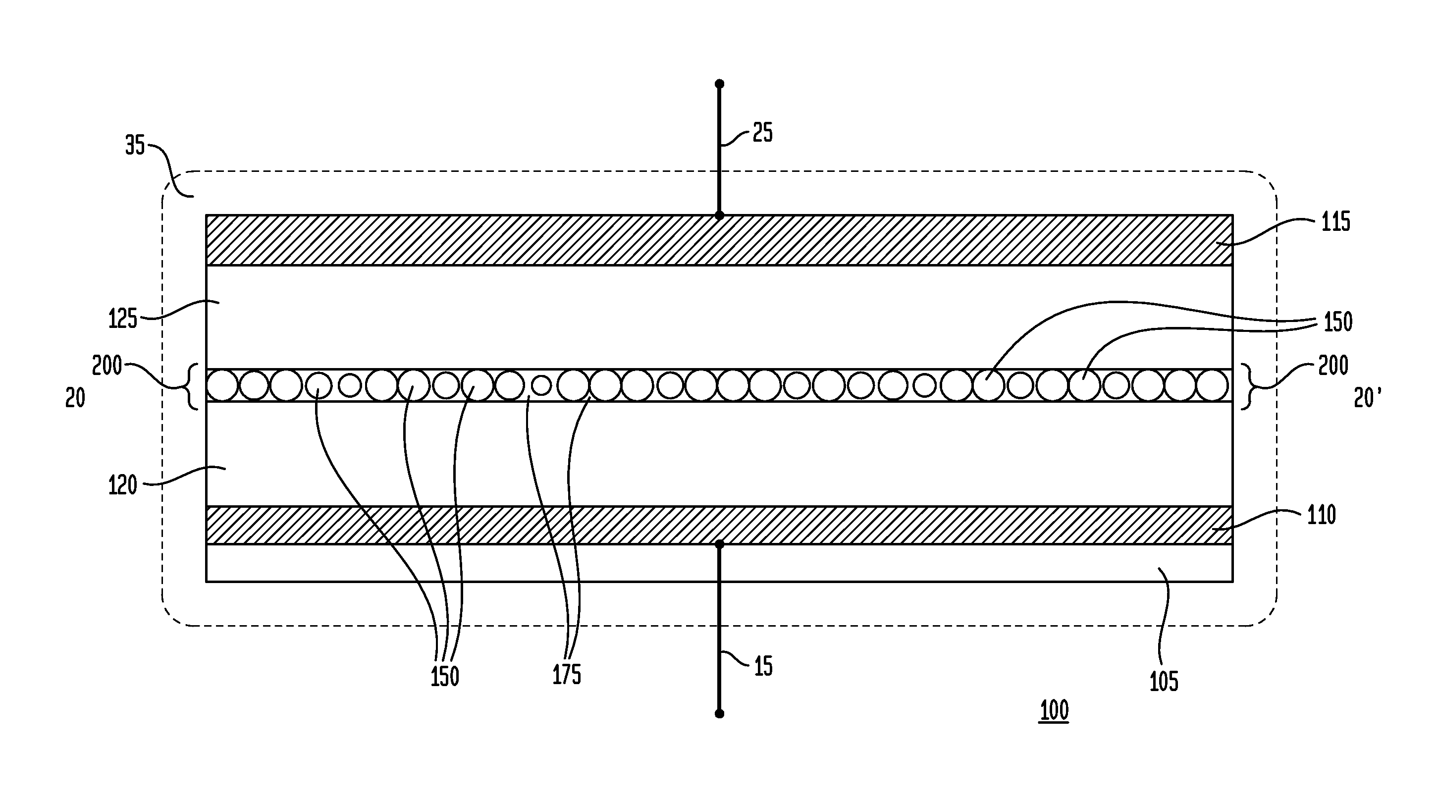
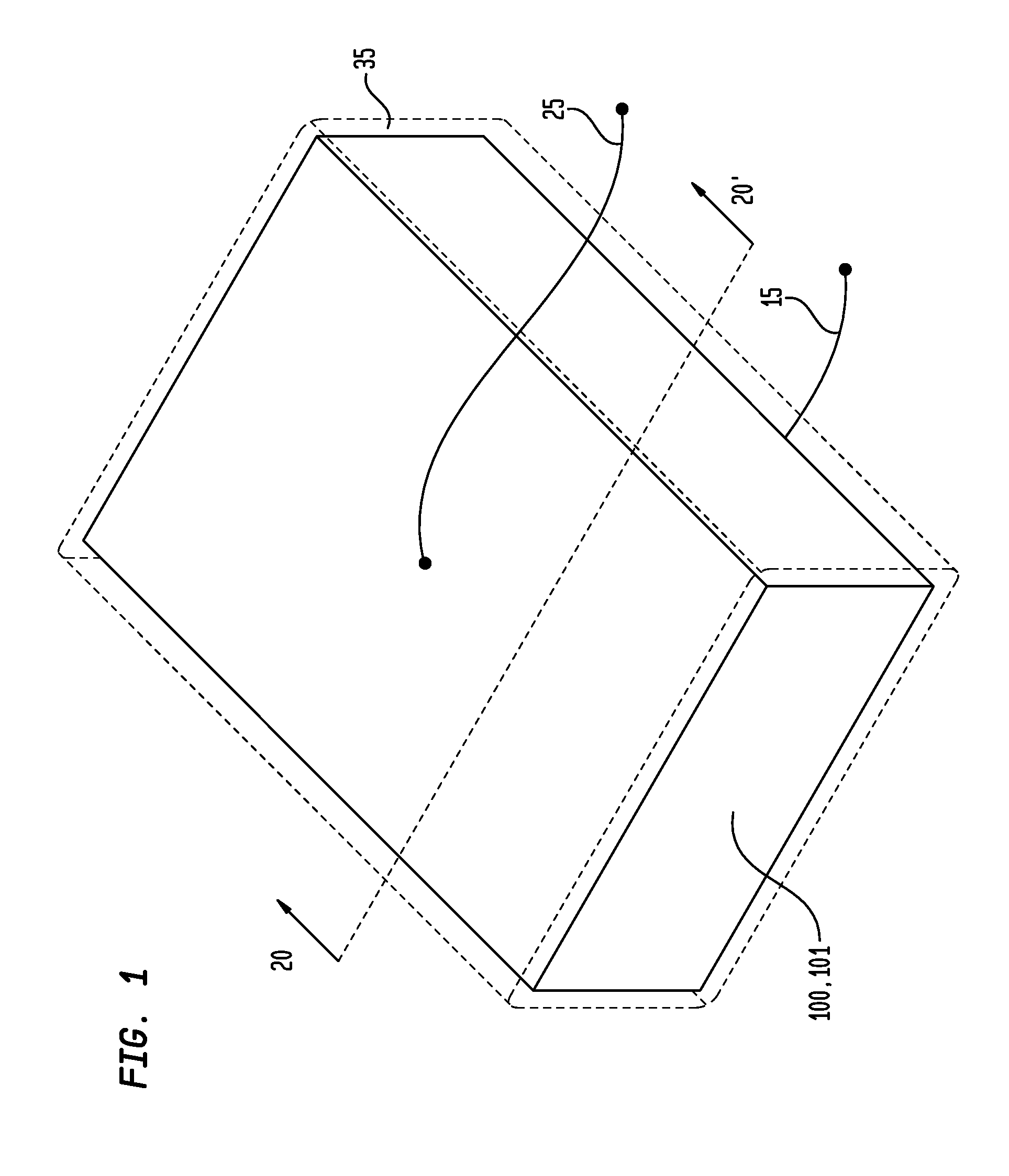
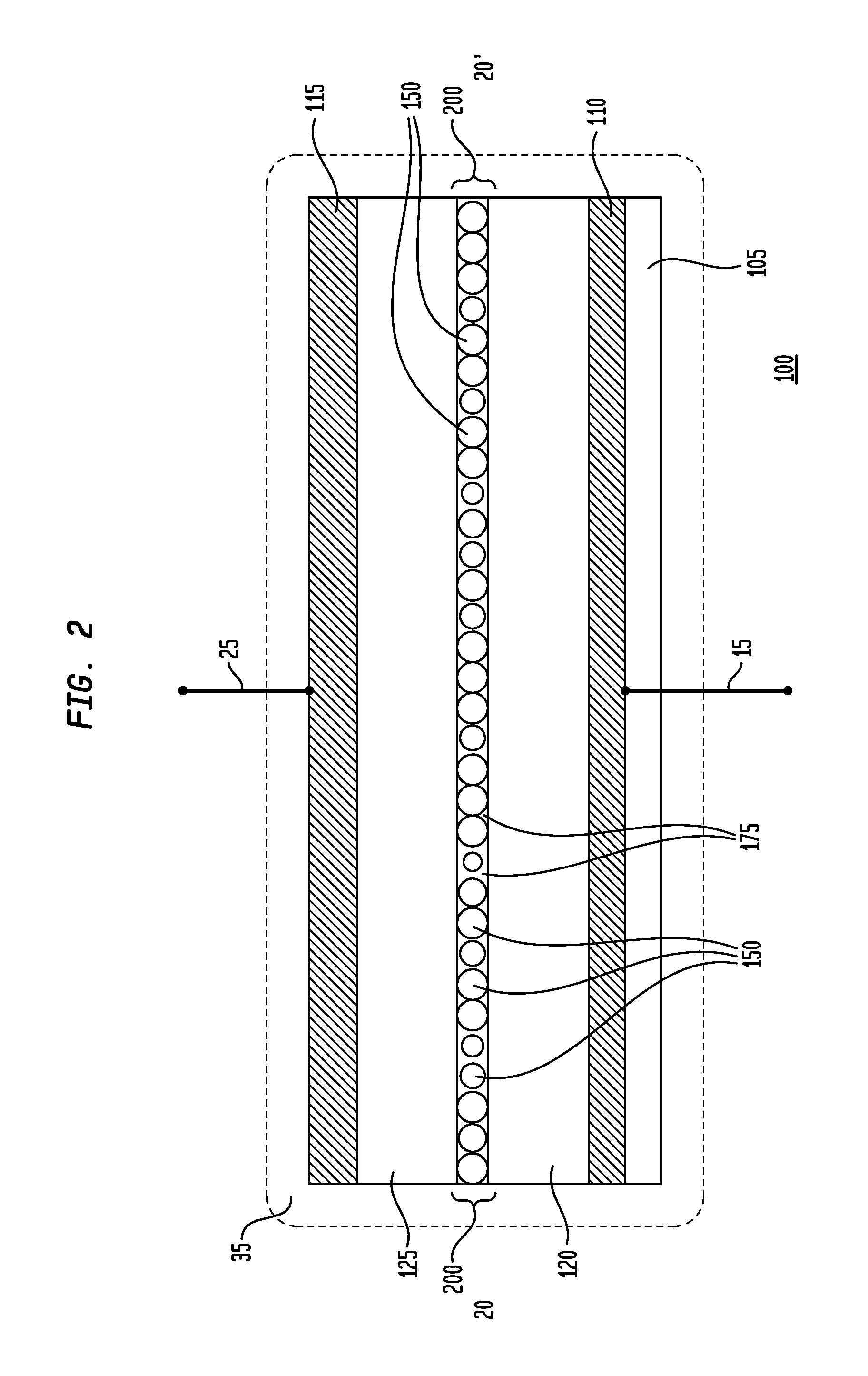
[0044]While the present disclosure is susceptible of embodiment in many different forms, there are shown in the drawings and will be described herein in detail specific exemplary or representative embodiments thereof, with the understanding that the present description is to be considered as an exemplification of the principles of the disclosure and is not intended to limit the invention or the disclosure to the specific embodiments illustrated. In this respect, before explaining at least one embodiment consistent with the present disclosure in detail, it is to be understood that the disclosure is not limited in its application to the details of construction and to the arrangements of components set forth above and below, illustrated in the drawings, or as described in the examples. Methods and apparatuses consistent with the present disclosure are capable of other embodiments and of being practiced and carried out in various ways. Also, it is to be understood that the phraseology a...


PUM


Abstract

Representative embodiments provide a composition for printing a liquid or gel separator utilized to separate and space apart first and second conductors or electrodes of an energy storage device, such as a battery or a supercapacitor. A representative composition comprises a plurality of particles, typically having a size (in any dimension) between about 0.5 to about 50 microns; a first, ionic liquid electrolyte; and a polymer or polymeric precursor. In another representative embodiment, the plurality of particles comprise diatoms, diatomaceous frustules, and / or diatomaceous fragments or remains. Another representative embodiment further comprises a second electrolyte different from the first electrolyte; the plurality of particles are comprised of silicate glass; the first and second electrolytes comprise zinc tetrafluoroborate salt in 1-ethyl-3-methylimidazolium tetrafluoroborate ionic liquid; and the polymer comprises polyvinyl alcohol (“PVA”) or polyvinylidene fluoride (“PVFD”). Additional components, such as additional electrolytes and solvents, may also be included.

Description

CROSS-REFERENCE TO A RELATED APPLICATION[0001]This application claims priority to and is a conversion of U.S. Provisional Patent Application Ser. No. 61 / 672,062, filed Jul. 16, 2012, inventor Vera Nicholaevna Lockett, entitled “Printable Ionic Gel Separation Layer For Energy Storage Devices”, which is commonly assigned herewith, the entire contents of which are incorporated herein by reference with the same full force and effect as if set forth in their entirety herein, and with priority claimed for all commonly disclosed subject matter.FIELD OF THE INVENTION[0002]The present invention in general is related to energy storage technology and, in particular, is related to separators between electrodes for energy storage devices such as supercapacitors and batteries, and more particularly, is related to printable gel separation layers having embedded structural components.BACKGROUND OF THE INVENTION[0003]Various discrete electrode separators or separation layers for energy storage devic...

Claims


Application Information

Patent Timeline
IPC IPC(8): H01M10/0565H01M2/14H01M2/16H01M50/403H01M50/414H01M50/426H01M50/437H01M50/443H01M50/491
CPCH01M10/0565H01M2/1653H01M2/145H01M2300/0085Y02E60/13H01G11/52Y02E60/10H01M50/403H01M50/437H01M50/414H01M50/491H01M50/443H01M50/426H01M10/0569H01M10/0568H01M10/0525H01G11/60H01G11/84H01M2300/0025H01M2300/0028H01G11/62H01M50/446H01M50/409H01M50/449H01M50/431H01M50/411H01M10/056
Inventor LOCKETT, VERA NICHOLAEVNALOWENTHAL, MARK DAVIDSHOTTON, NEIL O.RAY, WILLIAM JOHNSTONEKAMINS, THEODORE I.
Owner NTHDEGREE TECH WORLDWIDE
Learn More