
Continuous wave directional emission liquid crystal structures and devices

a liquid crystal structure and directional emission technology, applied in semiconductor lasers, discharge tubes luminescnet screens, instruments, etc., can solve the problems of difficult to obtain a single laser wavelength, difficult to construct a tunable laser, and difficulty in avoiding mode hopping and other problems, to achieve the effect of avoiding mode hopping

Inactive Publication Date: 2014-01-16
ALPHAMICRON INC
View PDF3 Cites 8 Cited by
  • Summary
  • Abstract
  • Description
  • Claims
  • Application Information

AI Technical Summary

Benefits of technology

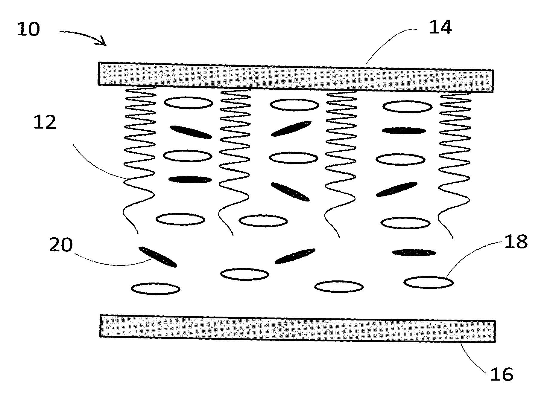
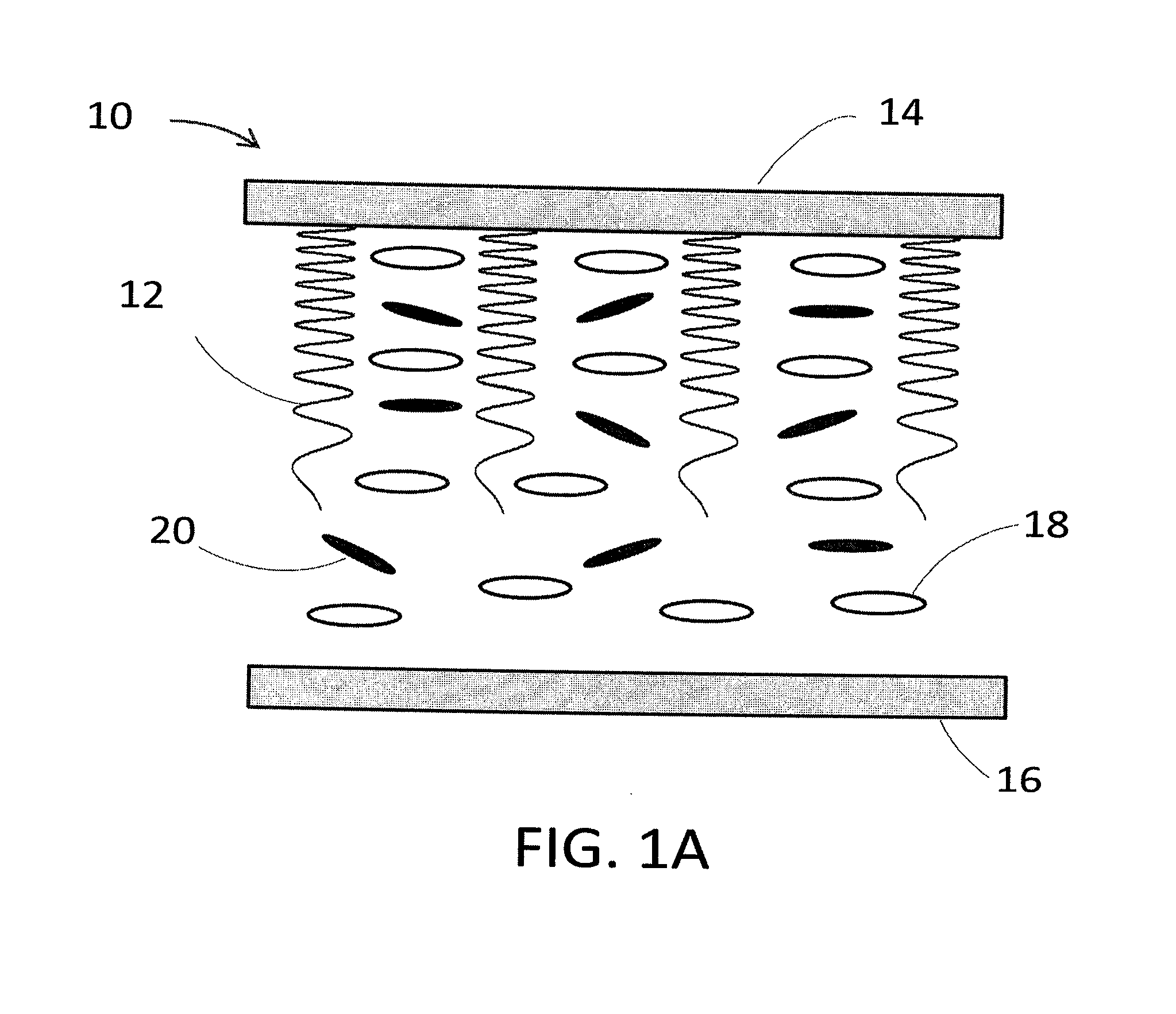
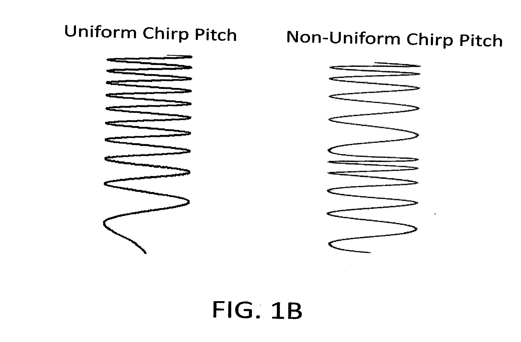
This patent describes a new way to use a special material called a light emitting PBG to create laser light. This material can be spun into a thin layer and excited by a laser or a LED to cause directional emission. The light emitting PBG material contains a polymer network with a non-uniform pitch, a small molecule liquid crystal with birefringence, and light emitting dyes that have low triplet state absorption. The excitation by a light source causes a directional electromagnetic emission from the material. The directional emission can be controlled by changing factors such as temperature, mechanical stress, and electric field. This patent also describes light emitting devices made by using the light emitting PBG material and a light source.

Problems solved by technology

Constructing a tunable laser is very difficult for a variety of reasons and is the subject of a significant amount of research in the laser science and technology field.
A drawback of dye lasers is the initial alignment of the cavity.
Since dye lasers provide a broadband emission, it is difficult to obtain a single laser wavelength and avoid artifacts such as mode hopping.
This drives up the cost and makes the laser bulky.
This has made these systems not applicable in industries where the operator is not a laser scientist or engineer.
Diode lasers have the drawback that they can only be operated at select, predetermined wavelengths and are not used in conjunction with amplifiers.
This has limited their use to low power applications.
To alter the wavelength, the complete laser system has to be changed which is a significant drawback for several applications.
However, these systems are expensive to fabricate and remain single wavelength with limited capability for true amplification.
Tunable, continuous wave (CW) CLC lasers are greatly desired but, despite many efforts they have not been realized.

Method used


Image

  • Continuous wave directional emission liquid crystal structures and devices
  • Continuous wave directional emission liquid crystal structures and devices
  • Continuous wave directional emission liquid crystal structures and devices

Examples


example

[0056]One example of a device according to the invention is described in this non-limiting example. In this example, we show the results of a new approach for achieving CLC directional emission using a material with a non-uniform reflection band across the cell thickness.

[0057]We selected a dye with both low absorption and low quantum yield in a triplet state such as outlined in Montejano, et al, J. Photochem. Photobiol. A. 181, 142 (2006). Polymer network was added to the system to allow for stability of the structure. This combination permitted us to achieve CW-CLC lasing.

[0058]There are several art recognized approaches to produce a non-uniform reflection band. Here, we used the non-limiting approach of a pitch gradient (see SEM images of CLC structures prepared by similar methods, such as those referenced in Broer, et al., “Wide-band reflective polarizers from cholesteric polymer networks with a pitch gradient”, Nature 378, 467-469 (1995)]; D. Katsis, “Circularly polarized photo...


PUM

PropertyMeasurementUnit
Temperatureaaaaaaaaaa
Density of statesaaaaaaaaaa
Wavelengthaaaaaaaaaa

Abstract

A light emitting photonic bandgap (PBG) material, and devices uses the same, having (a) a polymer network exhibiting a non-uniform pitch; (b) a small molecule liquid crystal material with a birefringence >0.04; and (c) one or more light emitting dyes having a low triplet state absorption. The light emitting PBG material has a defect-induced density of states enhancing feature at a wavelength that overlaps the emission spectrum of the light emitting dye. Excitation of the light emitting PBG material by a light source causes a directional electromagnetic emission from the light emitting material. The PBG material, and device, are capable of emitting continuous wave laser light as a result of excitation by a low-power incoherent light source.

Description

CROSS-REFERENCE TO RELATED APPLICATIONS[0001]This application claims priority to, and any other benefit of, U.S. Provisional Patent Application Ser. No. 61 / 670,177, filed on Jul. 11, 2012, entitled “CONTINUOUS WAVE DIRECTIONAL EMISSION LIQUID CRYSTAL STRUCTURES AND DEVICES,” the entire disclosure of which is fully incorporated herein by reference.BACKGROUND[0002]Low cost lasers which can operate in the continuous wave (CW) mode are of great interest and used in consumer electronics, medical, sensing, telecommunication and other industries. Each application uses particular wavelengths and as such lasers which can provide different emission wavelengths are of particular interest.[0003]Constructing a tunable laser is very difficult for a variety of reasons and is the subject of a significant amount of research in the laser science and technology field. For tunable lasers, typically dye lasers are used. These lasers are based, typically, on fluorescent dyes dissolved in an active medium...

Claims


Application Information

Patent Timeline
IPC IPC(8): C09K19/54G02F1/1335H05B33/14
CPCC09K19/542H05B33/14G02F1/1336C09K2019/546G02F1/1334G02F2202/32H01S3/08059H01S3/094034H01S3/1686H01S3/213G02B6/1225H01S5/11
Inventor MUNOZ, ANTONIOKOSA, TAMASLUCHETTE, PAULSUKHOMLINOVA, LUDMILLATAHERI, BAHMAN
Owner ALPHAMICRON INC
Learn More