
Light emitting diode primary optic for beam shaping

a technology of light emitting diodes and primary optics, which is applied in the direction of semiconductor devices for light sources, fixed installations, lighting and heating apparatus, etc., can solve the problems of incandescent lights being very energy-inefficient light sources, requiring a significant amount of ceiling space to operate properly, and still relatively inefficient, so as to improve light fixture emission and emission characteristics.

Active Publication Date: 2014-01-09
CREELED INC
View PDF5 Cites 8 Cited by
  • Summary
  • Abstract
  • Description
  • Claims
  • Application Information

AI Technical Summary

Benefits of technology

The patent is about LED components with special optics that improve their ability to emit light. It also discusses using these LED components in light fixtures to create better emissions.

Problems solved by technology

These fixtures can require a significant amount of ceiling space to operate properly.
Incandescent lights are very energy-inefficient light sources with approximately ninety percent of the electricity they consume being released as heat rather than light.
Fluorescent light bulbs are more energy efficient than incandescent light bulbs by a factor of about 10, but are still relatively inefficient.
In addition, LEDs can have a significantly longer operational lifetime.
Incandescent light bulbs have relatively short lifetimes, with some having a lifetime in the range of about 750-1000 hours.
Fluorescent bulbs can also have lifetimes longer than incandescent bulbs such as in the range of approximately 10,000-20,000 hours, but provide less desirable color emission.
One design challenge associated with LED-based multi-source luminaires is blending the light from LED sources within the luminaire so as to provide a uniform illuminance and color uniformity across the light emitting surfaces of the luminaire.
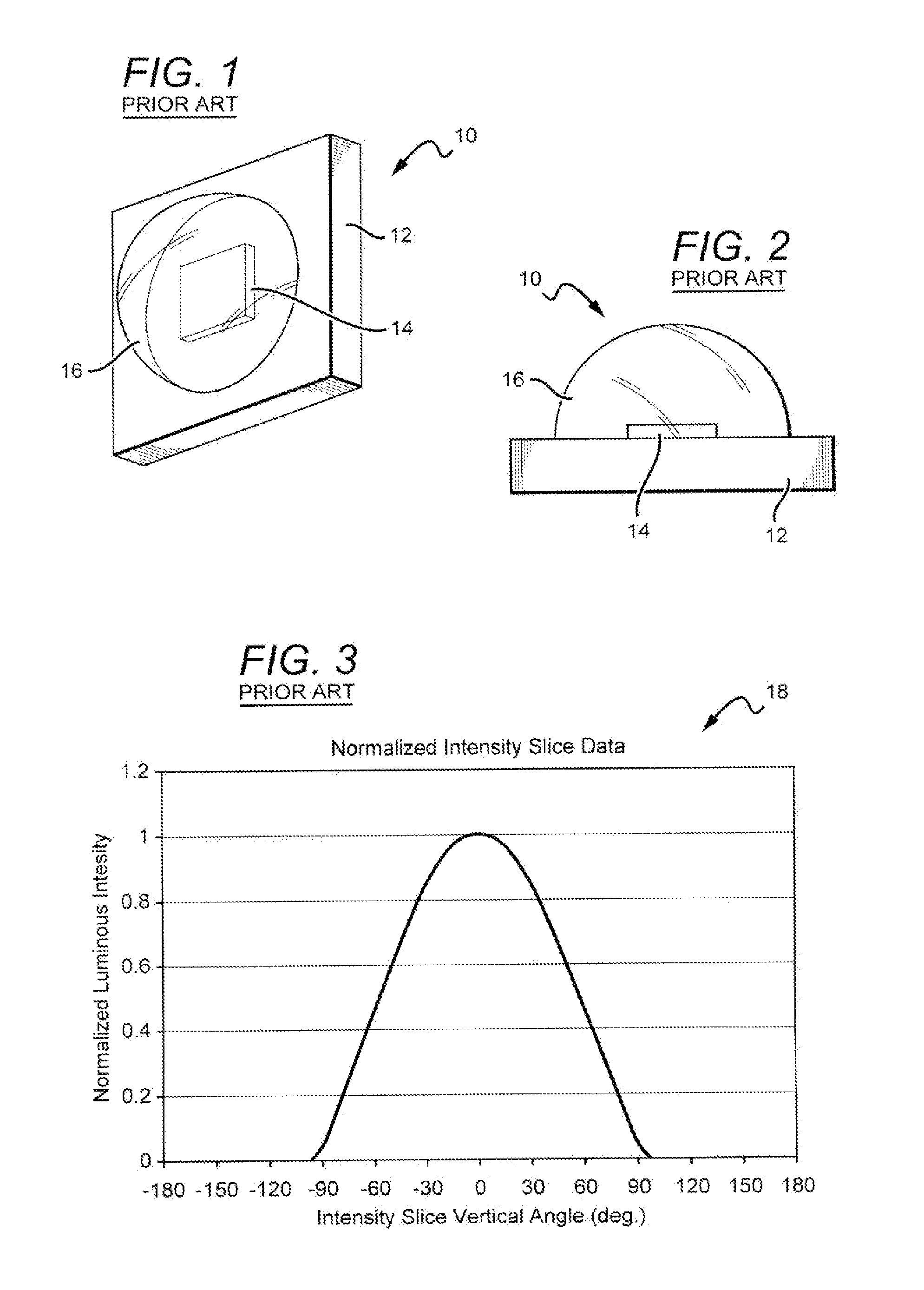
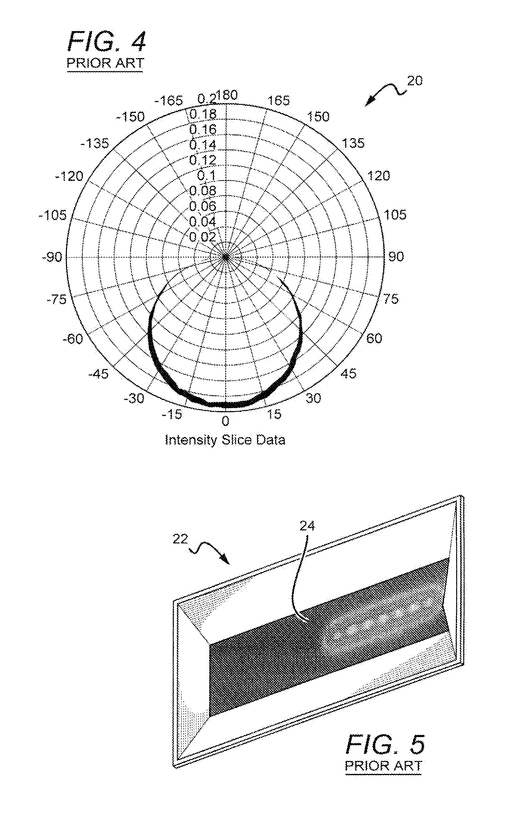
These emission profiles are relatively narrow with a peak that can result in undesirable near-field intensity and color variations across the emitting surface of the luminaire.
Such a non-uniform luminance distribution is generally considered to be aesthetically undesirable for most lighting applications.
Accordingly, standard LED components with standard primary optics may not be compatible with forward facing or direct backlighting.
This approach results in additional manufacturing complexities and costs, and can also result in efficiency losses due to both absorption in the secondary optic and Fresnel loss associated with the additional optical interfaces presented by the secondary optic.
However, in order to have a significant effect on the luminance distribution, it is generally necessary to provide a high degree of scattering—typically resulting in each light ray emitted by the LED component having multiple encounters with various internal surfaces of the luminaire.
This approach can lead to a significant loss in efficiency since such scattering surfaces are not ideal and each scattering event thus leads to light loss.
As in the case of direct view luminaires with heavily diffusing elements, interaction with multiple scattering elements within the luminaire body can result in optical losses, with the losses increasing with the number of interactions.

Method used


Image

  • Light emitting diode primary optic for beam shaping
  • Light emitting diode primary optic for beam shaping
  • Light emitting diode primary optic for beam shaping

Examples


Embodiment Construction

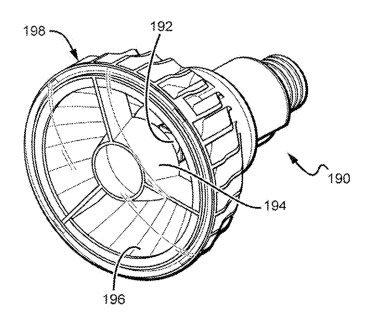
[0041]The present invention is generally directed to LED components having primary optics that make the LED components more compatible with direct emission light fixtures or luminaires, with one example being troffer-style light fixtures. The present invention utilizes custom primary optical elements as part of an LED package component which shapes the angular distribution of the light emitted by the package into a desired profile. Specifically, the different embodiments of the present invention can allow for the distribution of emitted light into angles typically not achieved with standard primary optical elements (which typically produce Lambertian or cosine-like beam profiles). Many applications such as backlighting and downlighting (e.g. troffers) benefit from the spreading or directing of the Lambertian LED beam profile into higher angles to reduce pixilation, or undesirable near-field intensity and color variations across the emitting surface of the backlight or troffer. This ...


PUM


Abstract

LED components are described having primary optics provide improved LED component emission characteristics. Light fixtures are also described that utilize the LED components to provide improved light fixture emissions. One LED component according to the present invention comprises an LED chip emitting an LED chip emission pattern. A primary optic is included directly on the LED chip with LED light from the LED chip passing through the primary optic. The primary optic shapes the LED emission pattern into an LED component emission pattern with the LED component emission pattern being broader than the LED chip emission pattern.

Description

BACKGROUND OF THE INVENTION[0001]1. Field of the Invention[0002]The invention relates to light emitting diodes (LED or LEDs) and LED components having primary optics for emission pattern shaping, and in particular for emission pattern broadening.[0003]2. Description of the Related Art[0004]Different LED light fixtures have been developed such as troffer-style fixtures that are used in commercial office and industrial spaces throughout the world. Previous troffers housed elongated fluorescent light bulbs that span the length of the troffer. Troffers may be mounted to or suspended from ceilings, such as being suspended by a “T-grid”. Often the troffer may be recessed into the ceiling, with the back side of the troffer (i.e. troffer pan) protruding into the plenum area above the ceiling a distance of up to six inches or more. In other arrangements, elements of the troffer on the back side dissipate heat generated by the light source into the plenum where air can be circulated to facili...

Claims


Application Information

Patent Timeline
Patent Type & Authority Applications(United States)
IPC IPC(8): F21V7/04F21V7/00
CPCF21S8/026H01L33/54F21V7/005F21V7/0008F21V13/04F21V29/74F21K9/233F21Y2115/10
Inventor TARSA, ERICHANSEN, MONICAKELLER, BERND
Owner CREELED INC
Learn More