
Polarizing lighting systems

a technology of lighting system and polarizer, which is applied in the direction of lighting and heating apparatus, instruments, spectral modifiers, etc., can solve the problems of increasing the difficulty of polarizing the ligh

Inactive Publication Date: 2014-01-09
YISSUM RES DEV CO OF THE HEBREWUNIVERSITY OF JERUSALEM LTD
View PDF6 Cites 57 Cited by
  • Summary
  • Abstract
  • Description
  • Claims
  • Application Information

AI Technical Summary

Benefits of technology

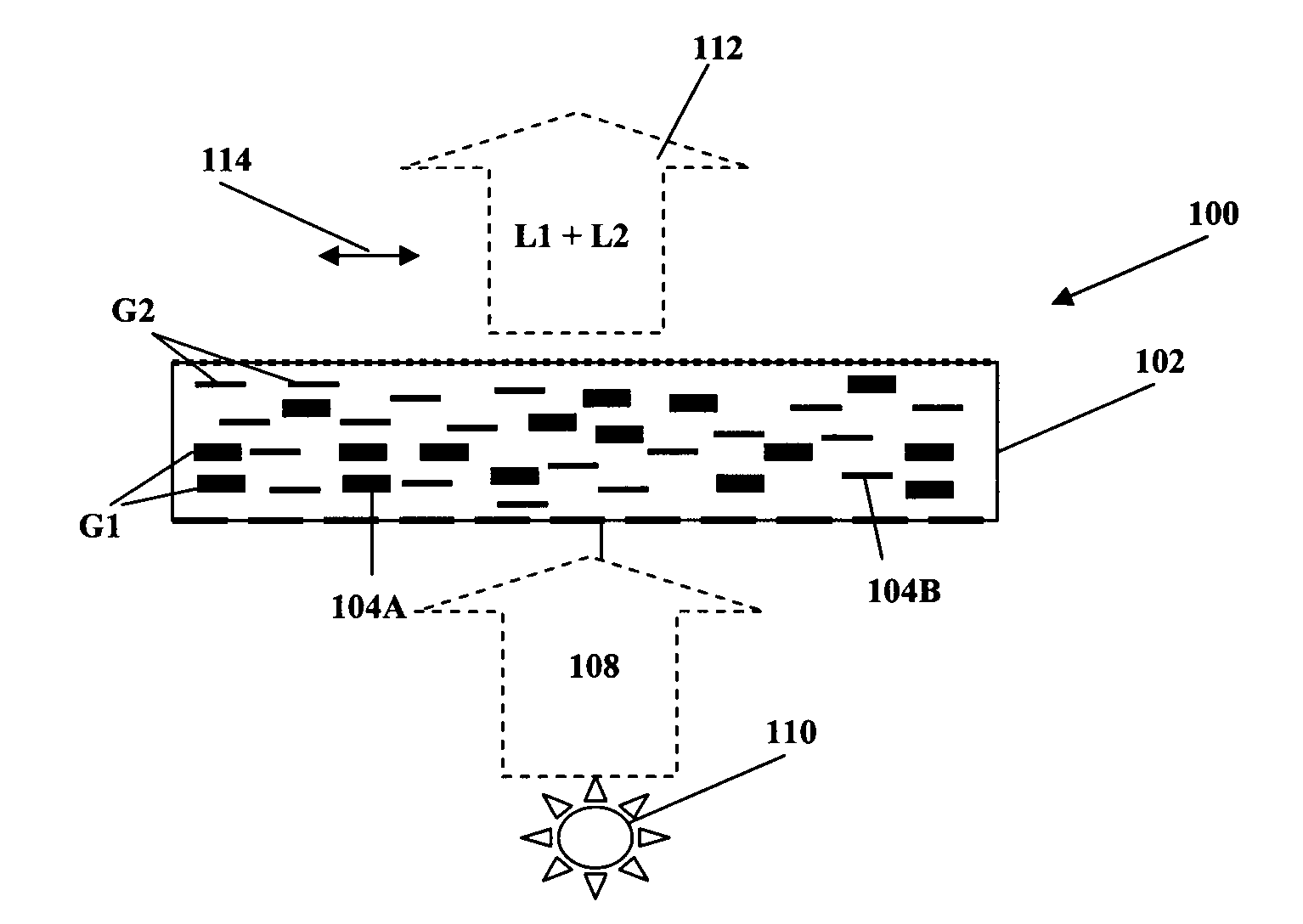
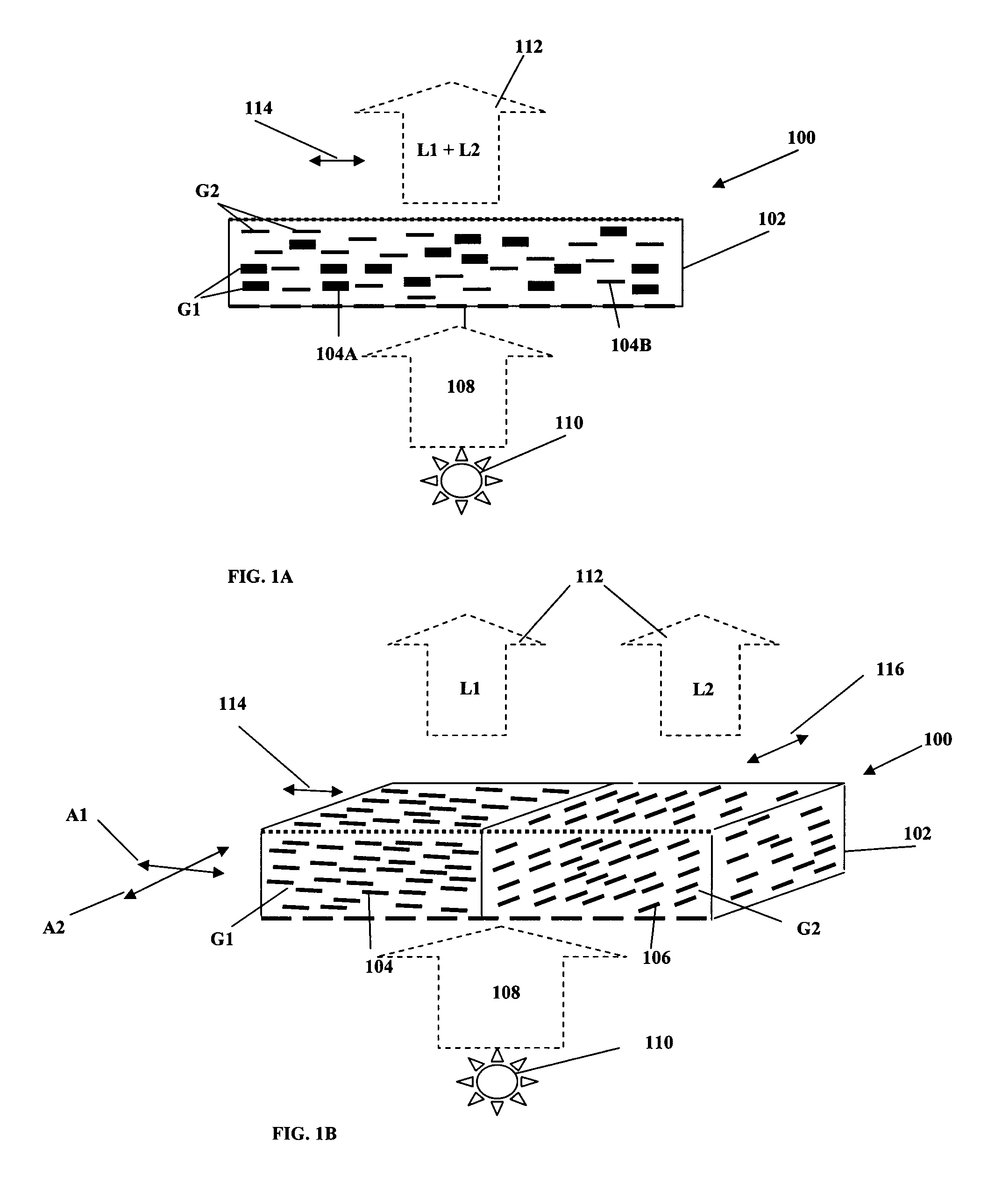
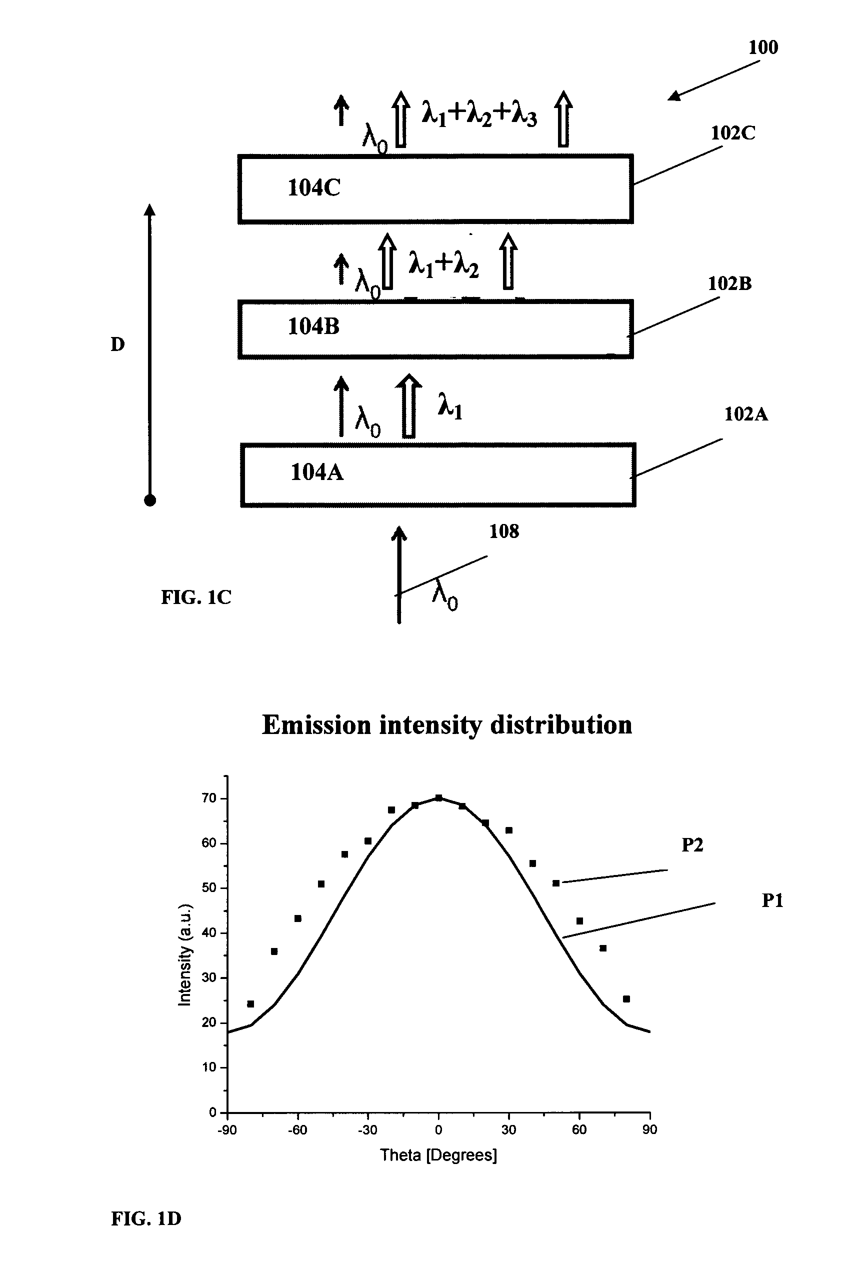
The present invention relates to a lighting device that uses nanorods for backlighting LCD display devices. The nanorods contain a film that can be incorporated into various LC based display / projection systems. The nanorods containing film emits light that has superior advantages in color quality, contrast, efficiency, and polarization as compared to traditional lighting devices. The nanorods film can replace expensive DBEF layers and provides higher brightness and efficiency of the lighting device. Various light extracting features and refraction index structures assist in the light extraction and polarization preservation. Polarization preserving diffuser film can be attached to the APEL from one or more sides. The film also includes various combinations of light dispersing particles of regular and non-regular shape that enhance the polarization properties. The technical effects of the invention include better color, contrast, and brightness enhancement of LCD display devices.

Problems solved by technology

The selection of a particular polarization using a polarizer comes at the cost of energy loss; approximately 50% of impinging light may be lost when using a simple passive (non-emissive) polarizer to provide polarized illumination using a non-polarized light source.
The problem is further intensified in mobile devices (laptops, cellphones, cameras, etc.) where battery life is a crucial factor.
However, such passive systems are complex and expensive to produce, as multiple (even tens) of layers are required for efficient recycling.
Passive approaches as described above complicate the design of a backlight system and are expensive.
They are also inactive in enhancing the quality of the color gamut of the emitted light, because they are wavelength dependent.
In fact, the need to preserve the color gamut of the original backlight complicates further the layer structure of backlight system.

Method used


Image

  • Polarizing lighting systems
  • Polarizing lighting systems
  • Polarizing lighting systems

Examples


example 1

[0085]An optically active structure comprising aligned nanorods within a polymer matrix was prepared. The rods were aligned within a polymer film by mechanical stretching of the polymer film. As a first step, the nanorods were mixed with a monomer solution of polyvinylbutyral (PVB, 200 mg) and toluene (2.4 ml). The nanorods concentration in the film was controlled by the amount added to the film, typically in the range of 0.5-3% by weight of the PVB weight. A non-scattering mixture could be obtained. A block was then cast from the polymer / nanorod melt into a mold and allowed to dry under vacuum for 12 hours, yielding a film of 1 inch in diameter and 0.4 mm thickness. For the stretching step, the block was placed in a mechanical stretching device. During the stretching the sample was heated to 110° by placing an Infra-red emission lamp in front of the sample. The sample was then stretched anistropically by pulling it slowly (0.5 mm / minute) in one direction. Once the film was elongate...

example 2

[0089]An optically active structure comprising stand-alone nanorods was prepared. The rods used were CdS rods with a CdSe seed, of dimensions 67×5 nm and emitting at 622 nm. The rods were aligned on a glass substrate or on polymer film. In a first method, nanorods were deposited on glass from solutions and were then aligned by a technique of rubbing by a velvet cloth. Alternatively, a solution of the rods was applied during the rubbing process. The velvet cloth directs the nanorods alignment preferentially along the direction of rubbing. This yields a layer with preferably aligned nanorods emitting light polarized preferably along the alignment axis. This could be used in a monochrome display.

[0090]A two-color back light unit for display that can be expanded to three color back light unit for display with the non-absorbed blue light emission passing through the film serving as the third color was demonstrated. A mixture of two samples of CdS rods with CdSe seeds of different dimensi...

example 3

[0094]An optically active structure comprising stand-alone nanorods was prepared. The rods were aligned on a glass substrate with patterned electrodes such as described in the above mentioned WO / 2010 / 095140 assigned to the assignee of the present application. In this method, nanorods were deposited on the glass from solutions while applying an alternating electric field between the electrodes. During drying of the solution, the nanorods were preferentially aligned parallel to the direction of the applied electric field. This yields a layer with preferably aligned nanorods emitting light polarized preferably along the alignment axis. Typical values for the polarization ratio were between 2 to 4.7, where each color emitter can have a different polarization ratio value according to the specific type of nanorod used, and the nanorods deposition and alignment conditions. To construct the back light unit, the above active anisotropic nanoparticle layer was placed on a blue emitting light ...


PUM

PropertyMeasurementUnit
thicknessaaaaaaaaaa
thicknessaaaaaaaaaa
aspect ratioaaaaaaaaaa

Abstract

An optically active structure (100) is provided, comprising at least two different groups (G1, G2) of optically active nanorods (104A, 104B). The groups of nanorods differ from one another in at least one of wavelength and polarization of light emitted thereby in response to pumping light. The nanorods of the same group are homogeneously aligned with a certain axis of alignment being substantially parallel or substantially perpendicular to an axis of alignment of the nanorods of at least one other group, such that the nanorods of said at least two groups have one or two axes of alignment. The optically active structure is used as colour polarized light source for displays.

Description

FIELD OF THE INVENTION[0001]This invention is generally in the field of polarizing lighting systems, and relates to optically pumped polarizing lighting systems, which are particularly useful as backlight systems for displays.BACKGROUND OF THE INVENTION[0002]Polarization properties of light are used in a variety of optical applications (products and methods) ranging from flat panel liquid-crystal displays (LCDs) to microscopy, metallurgy inspection and optical communication. Light generated by most light sources does not have a specific polarization, and typical polarization selection is done using polarizers of various types. The selection of a particular polarization using a polarizer comes at the cost of energy loss; approximately 50% of impinging light may be lost when using a simple passive (non-emissive) polarizer to provide polarized illumination using a non-polarized light source. This problem is of particular significance in backlight systems for LCD displays, where energy ...

Claims


Application Information

Patent Timeline
Patent Type & Authority Applications(United States)
IPC IPC(8): G02F1/1335
CPCG02F1/1336G02F1/133617G02F1/13362G02F1/133621G02F2202/36G02F2203/34G02F1/133614
Inventor BANIN, URIARBELL, HAGAI
Owner YISSUM RES DEV CO OF THE HEBREWUNIVERSITY OF JERUSALEM LTD
Learn More