
Check Valve and Method and Apparatus for Extending Life of Check Valve

Active Publication Date: 2014-01-02
COMPRESSOR PROD INT
View PDF4 Cites 7 Cited by
  • Summary
  • Abstract
  • Description
  • Claims
  • Application Information

AI Technical Summary

Benefits of technology

The invention is a device that prevents failures of check valves in equipment used in high-temperature, corrosive, or contaminated environments. The device provides a fluid barrier to protect the valves and helps extend their lifespan. It has a small internal volume to prevent delaying lubricant from reaching the compressor during start-up.

Problems solved by technology

For many years, the compressor industry has been replacing failed compressor check valves without understanding the cause of the failure.

Method used


Image

  • Check Valve and Method and Apparatus for Extending Life of Check Valve
  • Check Valve and Method and Apparatus for Extending Life of Check Valve
  • Check Valve and Method and Apparatus for Extending Life of Check Valve

Examples


Embodiment Construction

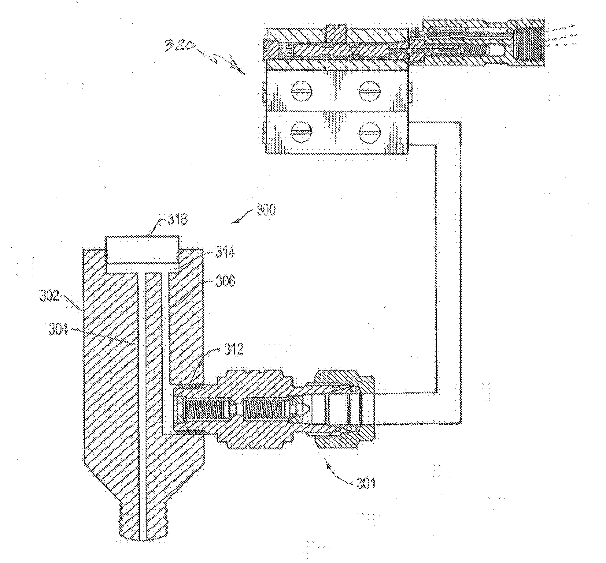
[0017]Applicant has found through his investigations of check valve failures in CNG compressors that check valves in compressors should preferably not be installed directly on the cylinder. Gas migrating into the check valve as it opens and closes can also create coking, that is, formation of carbon deposits from the lubricant, on the ball and seat of the check valve due to heat from the compressed gas or air. The coking causes premature failure of the valve. Vertical installation of the check valve allows the introduction of hot, contaminated gas into the check valve each time the valve opens to inject oil into the lubrication point, but failures can occur regardless of the orientation of the check valve on the cylinder.

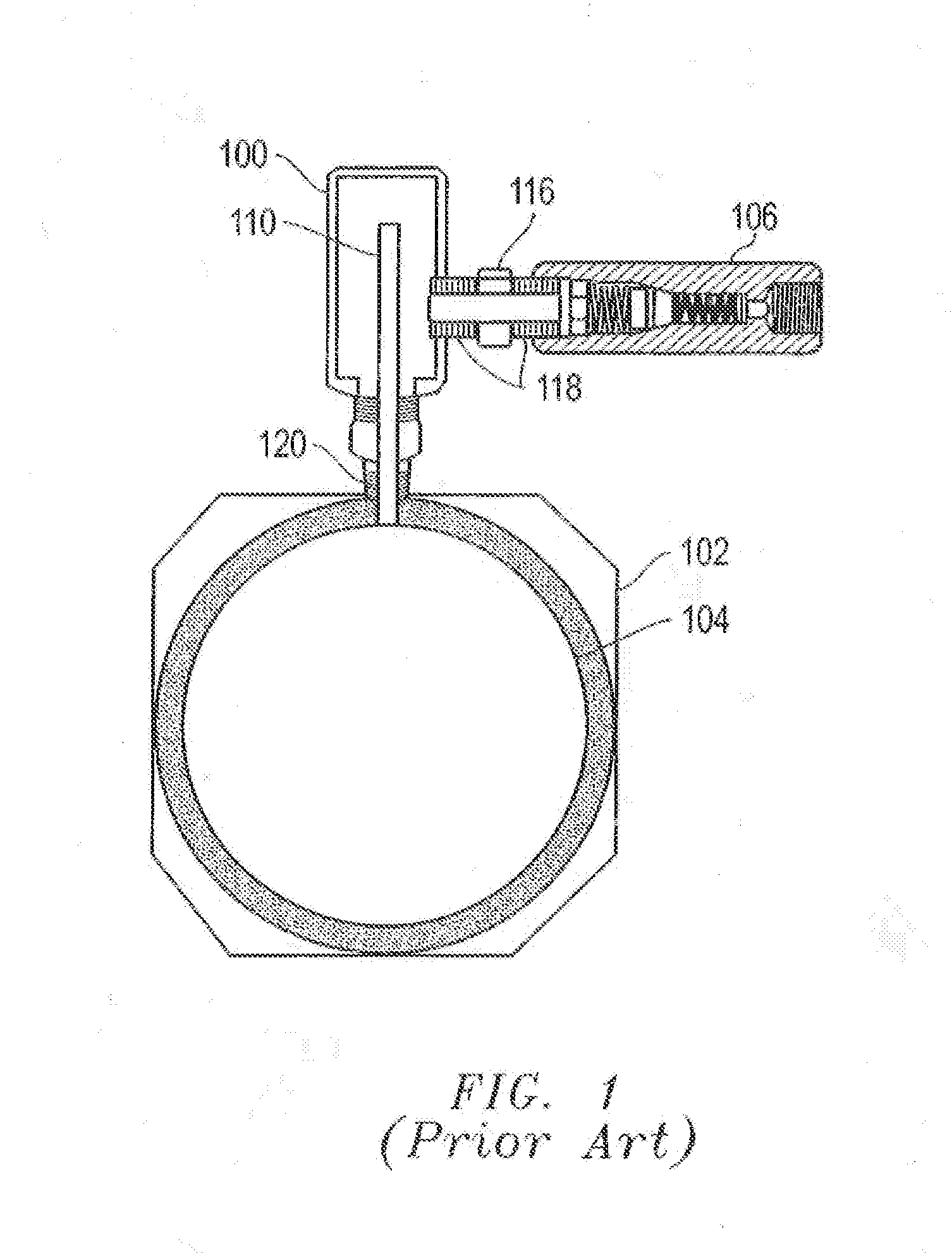
[0018]Applicant has found that the prior art reservoir device shown in FIG. 1, while providing some degree of protection compared to mounting the check valve directly on the compressor, has several drawbacks.

[0019]A. Volume of Oil

[0020]The interior volume of the var...


PUM


Abstract

A device and method are described for extending the life of check valves. An improved check valve having a double poppet and tapered guides is more robust, and a check valve protection device between the check valve and the environment into which fluid is injected protects the valve from a contaminating or corrosive environment. The check valve and check valve protection device are small and light weight to prevent vibration-induced failures. The check valve protection device preferably has an interior volume that fills quickly by relatively few cycles of the lubricant pump to reduce delay of lubricant to the injection point.

Description

[0001]This application is a Continuation of U.S. patent application Ser. No. 11 / 411,424 entitled “Check Valve and Method and Apparatus for Extending Life of Check Valve”, filed on Apr. 26, 2006, which claims priority from U.S. Prov. App. No. 60 / 675,142, filed Apr. 27, 2005, which is hereby incorporated by reference.TECHNICAL FIELD OF THE INVENTION[0002]The present invention relates to extending the life of check valves in hostile environments, and is particularly suitable for use in lubrication systems for natural gas compressors.BACKGROUND OF THE INVENTION[0003]Natural gas compressors receive natural gas from wells and compress the gas into compressed natural gas (“CNG”), which is more readily stored. Lubrication systems for natural gas compressors are described, for example, in U.S. Pat. No. 5,835,372 to Roys et al. To lubricate the compressor, a small volume of lubricant at high pressure is typically applied periodically into the compressor cylinder. A check valve inserted betwee...

Claims


Application Information

Patent Timeline
IPC IPC(8): F04B39/02
CPCF04B39/0223F04B39/0207F04B39/0284Y10T137/7868Y10T137/7846F04B39/0292
Inventor ROYS, CURTIS
Owner COMPRESSOR PROD INT
Learn More