Foot Actuated Percussion Board

Inactive Publication Date: 2014-01-02
GULAK LOREN R
View PDF1 Cites 12 Cited by
  • Summary
  • Abstract
  • Description
  • Claims
  • Application Information

AI Technical Summary

Benefits of technology

The present invention is a foot actuated musical device that allows a musician to generate a sound that closely matches the sound of an actual bass drum. The device is designed ergonomically to reduce strain on the musician's shin and ankle, making it comfortable to play for long periods of time. The device allows the musician's foot to remain in constant contact with the device, providing a more controlled rhythm like an actual foot pedal of a bass drum. Additionally, the invention provides a simple, lightweight, and easily transportable device for musicians to use in their music to achieve a high quality non-prerecorded bass drum sound.

Problems solved by technology

First, conventional stomp boxes do not match the sound wave signature of an actual bass drum being struck by a foot pedal beater.
Second, repetitive tapping by the musician on the box may cause strain in the musician's shin and / or ankle.
Third, some musicians have difficultly controlling the frequency or rhythm of the tapping because contact between the foot and stomp box is lost thereby increasing the risk of an undesired sound.

Method used


Image

  • Foot Actuated Percussion Board
  • Foot Actuated Percussion Board
  • Foot Actuated Percussion Board

Examples


first embodiment

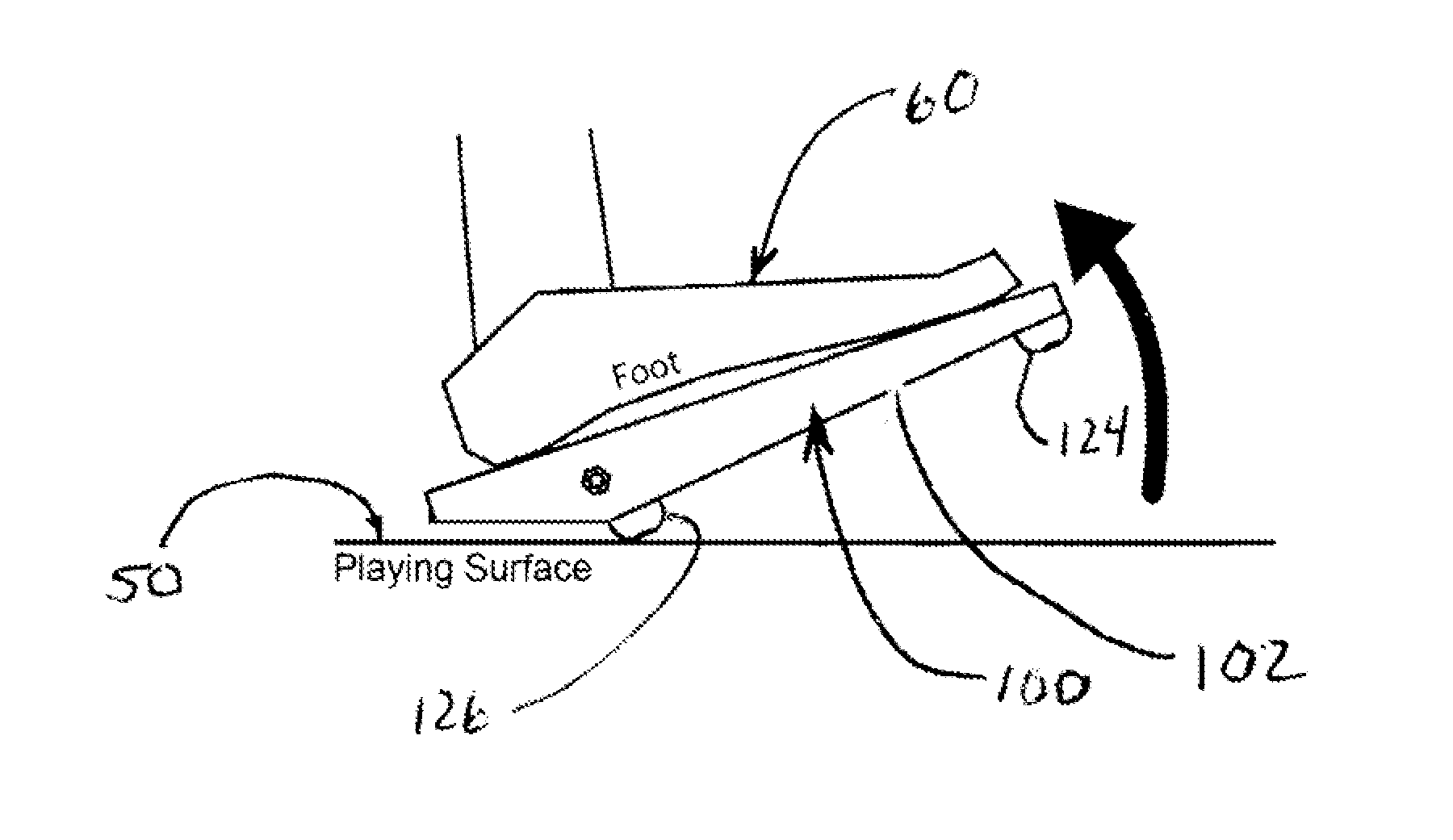
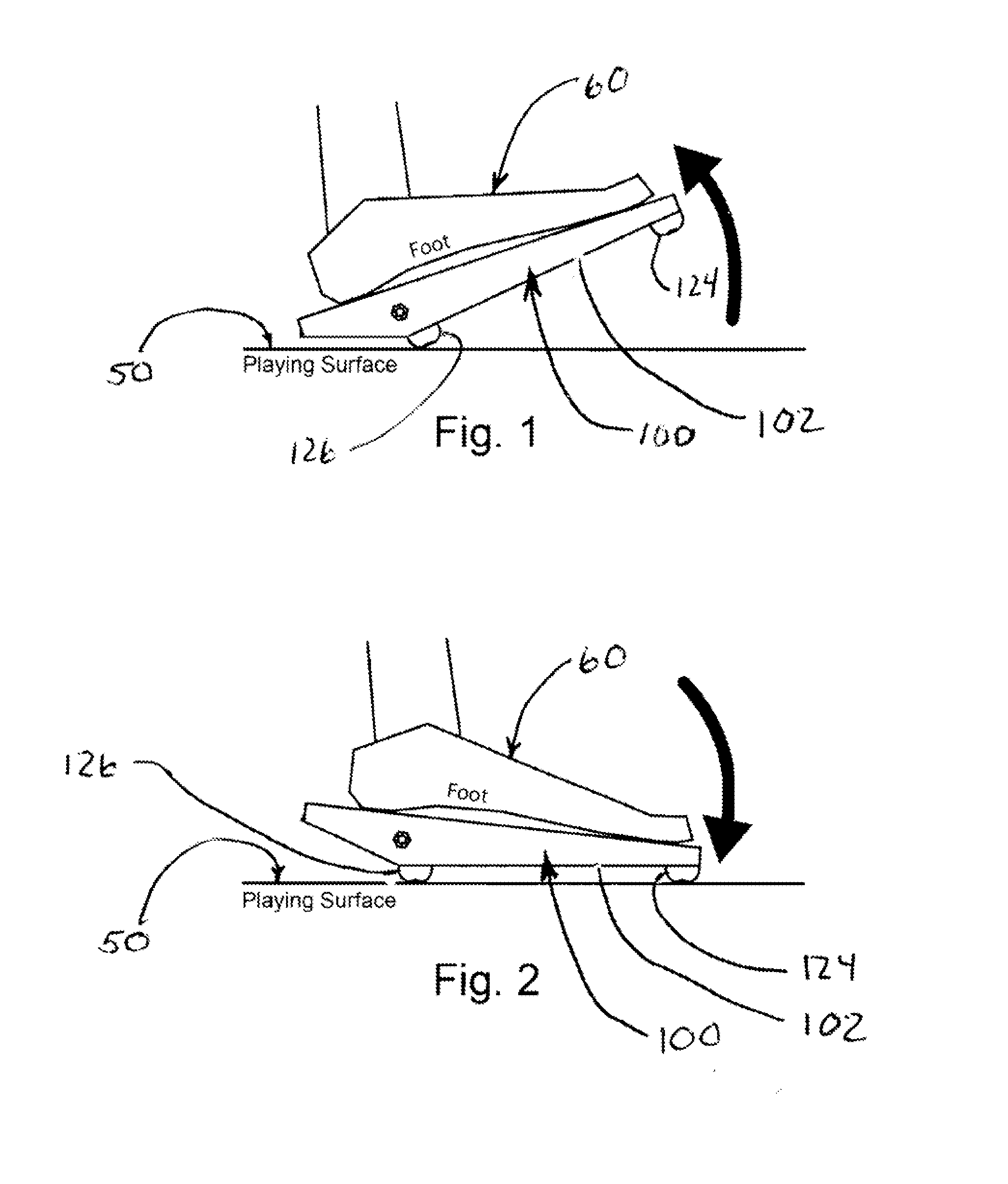
[0031]Referring to FIGS. 1 and 2, a device 100 according to the present invention is shown for use on a playing surface 50 by a musician (not shown) having a foot 60 to generate an electrical signal indicative of a bass drum. Device 100 generally comprises a body 102, a strike body 124, and a pivot body 126 adapted to rest upon playing surface 50 allowing body 102 to pivot relative to playing surface 50 between a first position where strike body 124 is off playing surface 50 (FIG. 1) and a second position where strike body 124 hits or impacts playing surface 50 (FIG. 2). Device 100 further comprises electronic sensing circuitry 130 (to be described) engaged with body 102 and adapted to generate an electrical signal indicative of a base drum in response to strike body 124 hitting playing surface 50.

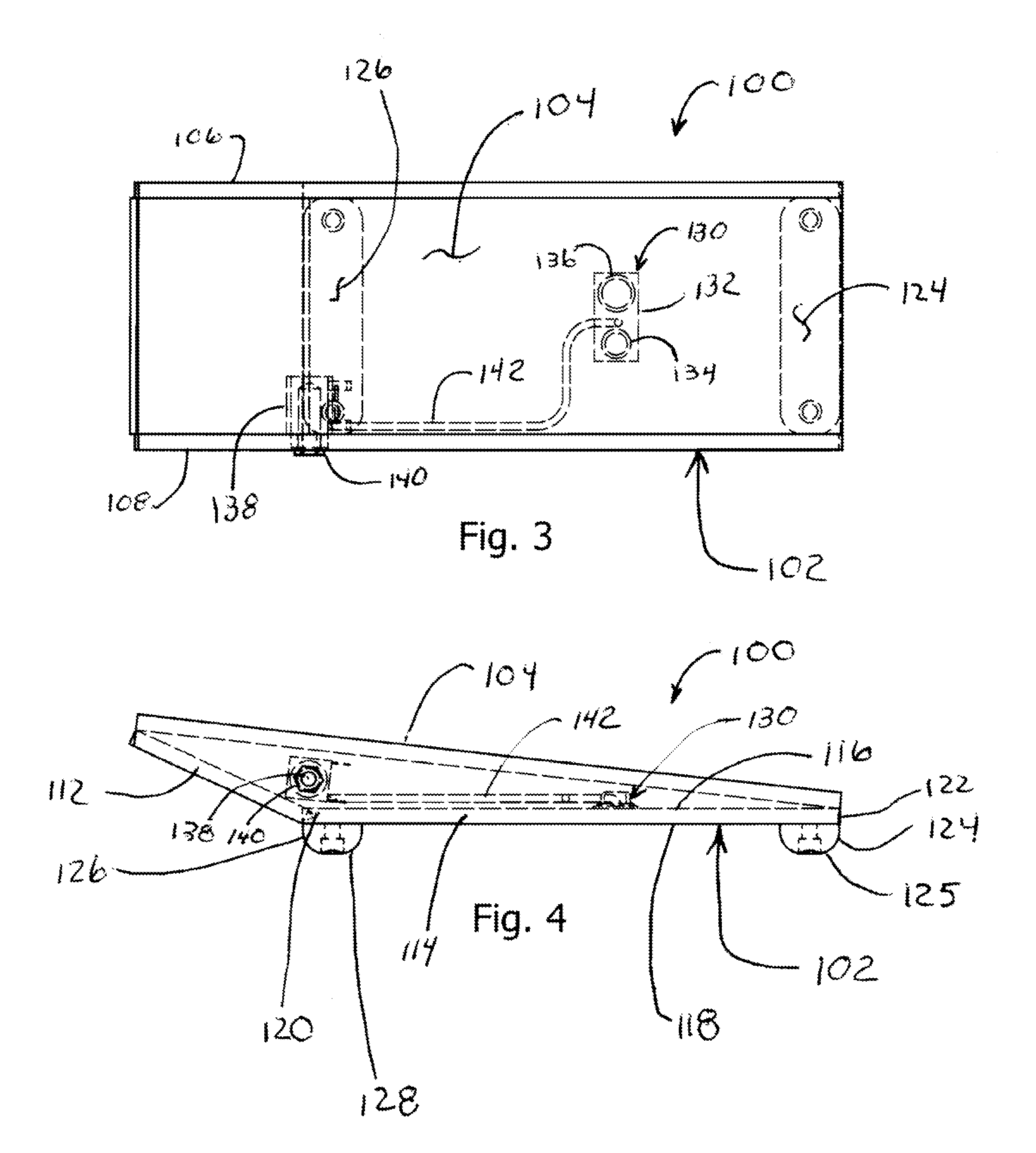
[0032]Referring to FIGS. 3-5, body 102 generally comprises a foot board 104, side boards 106 and 108, a back board 112, and a base 114. Side board 108 has an opening 110 adapted to receive...

second embodiment

[0038]Referring to FIGS. 9-11, a device 200 according to the present invention is shown for use on a playing surface 50 by a musician having a foot 60 to generate an electrical signal indicative of a bass drum. Device 200 generally comprises an elongated board or base 202, a pivot body 216, and a strike body 246. Device 200 further comprises an electronic sensing circuitry 274 (to be described) that is mounted within strike body 246 to generate an electrical signal indicative of a bass drum when strike body 246 hits or impacts playing surface 50.

[0039]With continued reference to FIGS. 9-11, base 202 comprises substantially planar top and bottom surfaces 204 and 206, a first or rear end 208, a second or front end 210, and left and right sides 212 and 214. Top surface 204 is substantially parallel to bottom surface 206 and receives the foot (not shown) of a musician to actuate device 200. Bottom surface 206 is inclined about three (3) degrees to playing surface 50 to assist in pivotin...

third embodiment

[0045]Referring to FIG. 19, where a device 300 according to the present invention is illustrated. Device 300 is similar to device 100 except the pivot body and the strike body have been replaced with rubber pivot pad 302 and rubber strike pad 304.


PUM


Abstract

The present invention is a device for use on a playing surface by a musician using a foot to generate an electrical signal indicative of a bass drum. The device generally comprises a body having a horizontally disposed base, a pivot body secured to the bottom surface of the base, and a strike body secured to the base. The pivot body is adapted to rest upon playing surface allowing body to pivot relative to the playing surface between a first position where the strike body is off the playing surface and a second position where the strike body hits or impacts the playing surface. The device further comprises electronic sensing circuitry adapted to generate an electrical signal indicative of a base drum in response to the strike body hitting the playing surface.

Description

CROSS-REFERENCE TO RELATED APPLICATIONS[0001]This application claims priority to U.S. Provisional Application Ser. No. 61 / 666,891 filed on Jul. 1, 2012, now pending, which is hereby incorporated in its entirety into this specification.BACKGROUND OF THE INVENTION[0002]Stomp boxes are widely used by musicians to add a sound of a bass drum while playing an instrument such as a guitar. Conventional stomp boxes are played by the musician tapping her foot on the box that causes a vibration sensor to generate an electrical signal similar to a bass drum. Conventional stomp boxes have several drawbacks. First, conventional stomp boxes do not match the sound wave signature of an actual bass drum being struck by a foot pedal beater. Second, repetitive tapping by the musician on the box may cause strain in the musician's shin and / or ankle. Third, some musicians have difficultly controlling the frequency or rhythm of the tapping because contact between the foot and stomp box is lost thereby incr...

Claims


Application Information

Patent Timeline
IPC IPC(8): G10H3/14
CPCG10H3/146G10H1/348
Inventor GULAK, LOREN R.
Owner GULAK LOREN R
Why Eureka
Try Eureka