
Two-phase cooling system for electronic components

a technology of electronic components and cooling systems, applied in the direction of laminated elements, semiconductor/solid-state device details, lighting and heating apparatus, etc., can solve the problems of increasing the amount of undesired waste heat that needs to be extracted, increasing the power density, and increasing the heat flux of such electric installations

Inactive Publication Date: 2013-12-26
ABB (SCHWEIZ) AG
View PDF34 Cites 29 Cited by
  • Summary
  • Abstract
  • Description
  • Claims
  • Application Information

AI Technical Summary

Benefits of technology

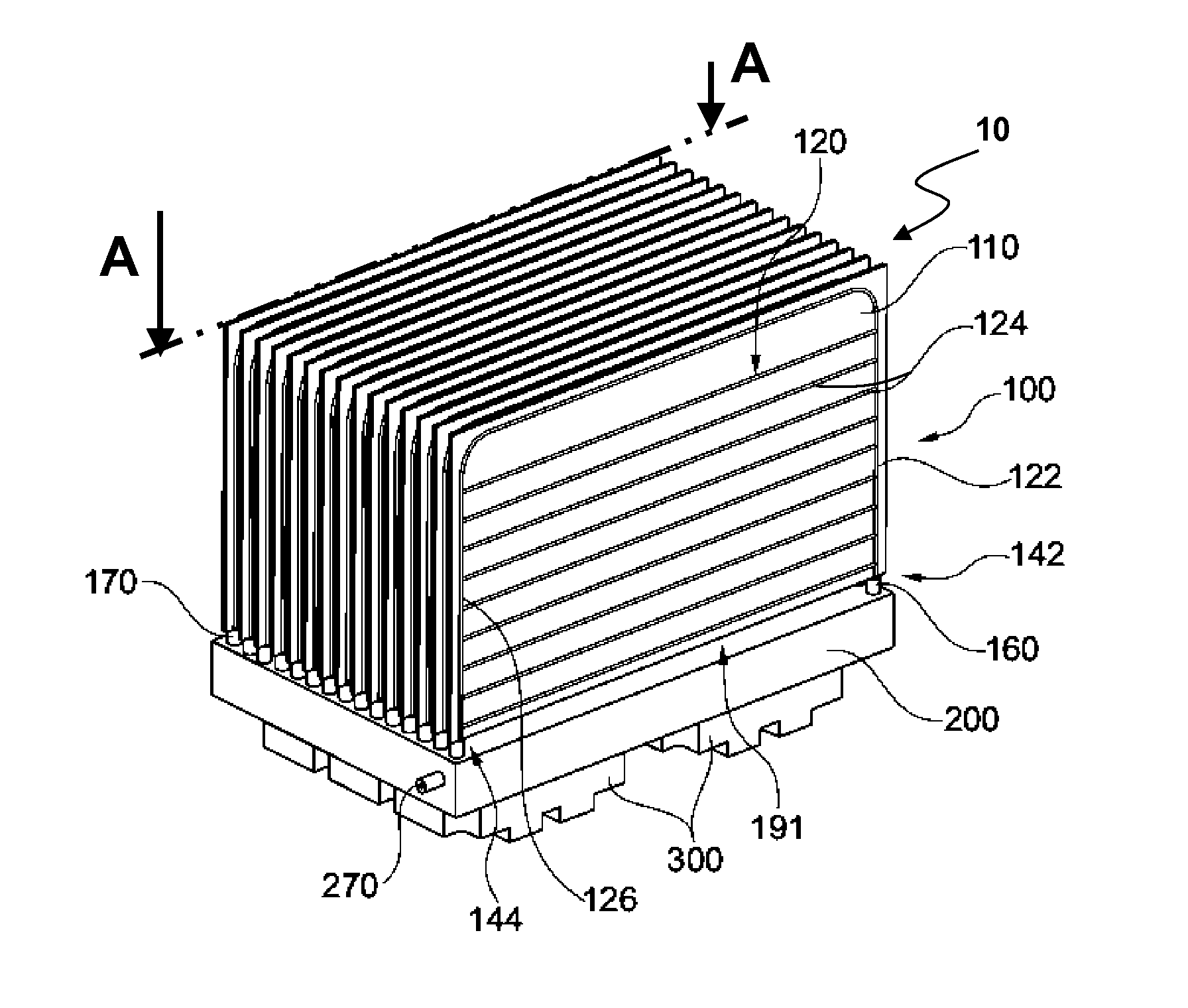
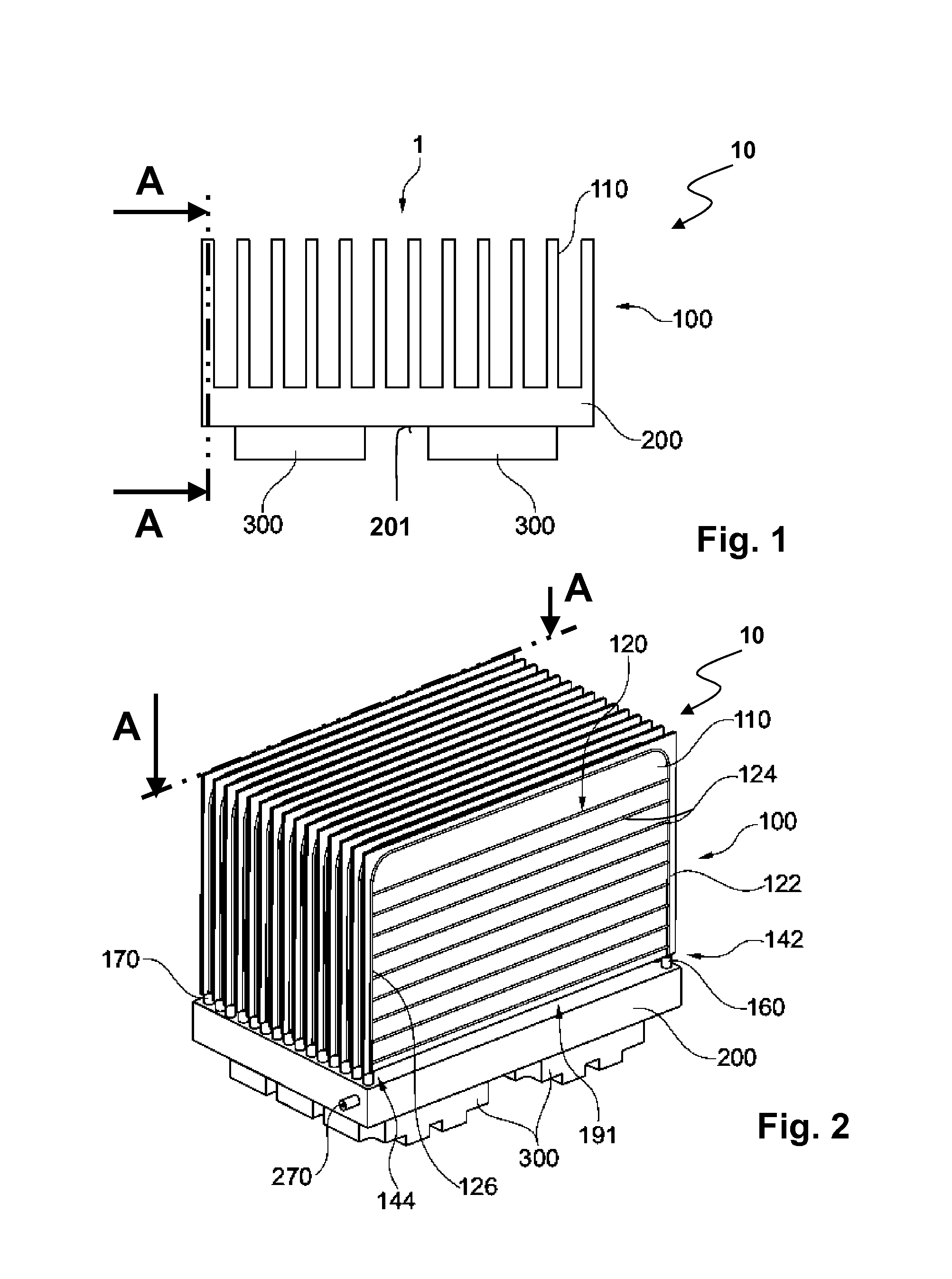
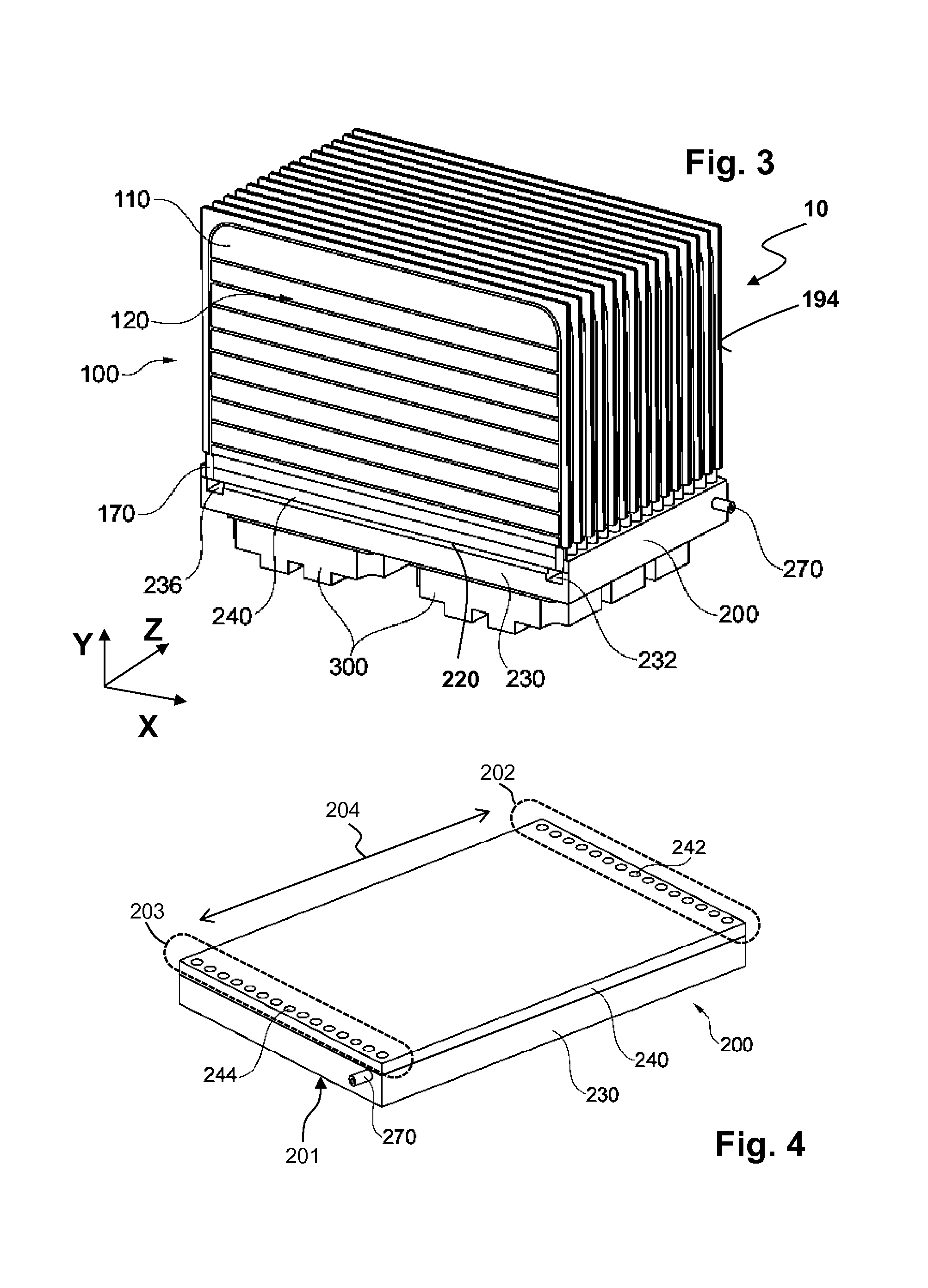
The patent describes a heat exchanger designed to cool electronic and electric components. The heat exchanger has a condenser body made of roll-bonded panels with a first channel and an evaporator body with a second channel. The panels are connected to each other to form the channels. The evaporator body has a thermal connection surface for the components to connect to. The first and second channels form a loop to transfer the heat from the components to the condenser body. The heat exchanger can efficiently cool electronic and electric components during operation.

Problems solved by technology

The result of these normally contravening demands can be an ever increasing amount of undesired waste heat needs to be extracted out of such installations and emitted to suitable thermal carriers such as air streams or water cycles that can be tied to powerful cooling devices.
In other words, the more compact the installation, the larger the power density and thus the larger the heat flux of such electric installations.
A drawback of water-cooled systems resides in that they can be costly, prone to leakage and can require at least one pumping device.
Because pumps can have moving parts that can be subject to attrition, the pumps can have a finite span of life and require maintenance and service.
A further drawback resides in down time of the whole installation in case of a sudden breakdown of the pump or during its maintenance, leading to undesired losses of income.
A drawback of common air cooling systems resides in that a large fin surface is used if the heat transfer coefficient between fin surface and air is low.
In addition, the higher the velocity of the air stream, the higher the pressure drop and the higher the level of acoustic noise caused by the fan needed to convey the air.
As a result of that measure, known air cooling systems and thus whole electric installations can become rather bulky because the heat sinks have usually long, thick and consequently heavy cooling fins sticking into the air stream for ensuring an acceptable fin efficiency, i.e. acceptable heat conveyance.
If the inter-fin channel width is small, then these inter-fin channels can be prone to clogging in dirty air environment such as heavy industry or railway.
Moreover the bulkiness of the overall electric installation contravenes the ongoing trend to miniaturized equipment.
Although the second concept is thermally efficient and utilizes structurally less complex designs and assembly than the first concept, the second concept can be difficult to manufacture in an economic way.

Method used


Image

  • Two-phase cooling system for electronic components
  • Two-phase cooling system for electronic components
  • Two-phase cooling system for electronic components

Examples


Embodiment Construction

[0025]Exemplary embodiments of the present disclosure can simplify the mechanical connection in between the roll-bonded panels and the base plate of a two-phase thermosiphon such that a more economic manufacturing process is achievable.

[0026]An exemplary embodiment of the two-phase heat exchanger according to the disclosure for cooling at least one of an electronic and / or an electric component according to the disclosure includes a condenser body that is thermally connected to an evaporator body. The condenser body includes a roll-bonded panel where a first channel for a phase-changing working fluid is arranged in between a first and a second sheet such that a first connection port delimits the first channel at one end and that a second connection port delimits the first channel at another end. The first sheet is connected to the second sheet by roll-bonding such that a roll-bonded panel is formed. The evaporator body includes a second channel, wherein the second channel is delimite...


PUM


Abstract

A two-phase heat exchanger for cooling at least one electronic and / or electric component includes an evaporator and a condenser. The evaporator transfers heat from the electronic and / or electric component to a working fluid. The condenser includes a roll-bonded panel, which has a first channel which has a first connection port and a second connection port. The evaporator has a second channel and first connection openings and second connection openings. The first connection port of the first channel is connected to one first connection opening of the evaporator and the second connection port of the first channel is connected to one second connection opening of the evaporator and the working fluid is provided to convey heat by convection from the evaporator to the condenser by flowing from the second channel through the first connection opening or the second connection opening of the evaporator towards the first channel.

Description

RELATED APPLICATION(S)[0001]This application claims priority under 35 U.S.C. §119 to European Patent Application No. 12172752.3 filed in Europe on Jun. 20, 2012, the entire content of which is hereby incorporated by reference in its entirety.FIELD[0002]The disclosure relates to the cooling of electronic and electric components. For example, the disclosure relates to a two-phase heat exchanger including an evaporator and a condenser for cooling at least one electronic and / or electric component, a power module with an electronic and / or electric component and a two-phase heat exchanger and the use of a power module with such a heat exchanger for cooling an electric and / or electronic component in a vehicle.BACKGROUND INFORMATION[0003]In the field of electric and electronic devices, efficient cooling systems can be used to take up heat and convey the heat resulting from ohmic losses and switching losses of the electric and / or electronic components in order to prevent excessive overheatin...

Claims


Application Information

Patent Timeline
IPC IPC(8): H05K7/20
CPCH05K7/20309H05K7/20318F28F3/14F28D15/0266F28D15/0275H01L23/427H01L23/3672H05K7/20936H01L2924/0002H01L2924/00
Inventor AGOSTINI, FRANCESCOFABBRI, MATTEOGRADINGER, THOMAS
Owner ABB (SCHWEIZ) AG
Learn More